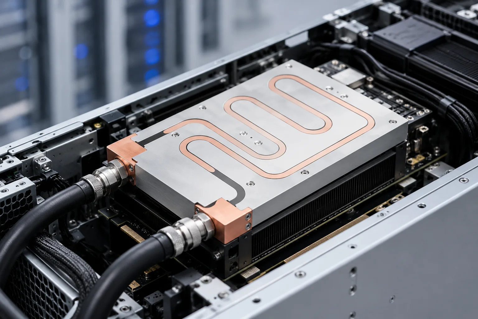
An energy storage liquid cooling plate should do more than remove heat from a battery module.
In an ESS, dozens or even hundreds of cells and multiple battery modules operate together over long charge and discharge cycles. The cooling system therefore has to manage not only maximum temperature, but also temperature distribution across the battery assembly.
For energy storage systems, a well-designed liquid cooling plate should control battery temperature uniformly while keeping coolant flow, pressure drop, pumping demand, sealing, and mechanical integration within practical system limits.
That changes the design objective.
The engineer is not trying to create the coldest possible plate. The goal is to create a stable thermal environment that can be reproduced across multiple modules and cooling branches.
For custom ESS projects, liquid cold plate solutions can be developed around battery-module geometry, thermal load, coolant conditions, available pressure, and production requirements.
Design the Thermal Architecture From the Battery Module Outward
A useful ESS cooling design starts with the battery module—not the coolant channel.
The thermal path can be simplified as:
Battery Cell
→ Module Structure
→ Thermal Interface
→ Cooling Plate Surface
→ Internal Coolant Channel
→ Module Branch
→ Rack Manifold
→ ESS Cooling Loop
A problem at any point can reduce the effectiveness of the complete system.
For example:
- Poor module contact increases interface resistance.
- A poorly positioned flow channel creates local hot zones.
- Excessive pressure drop reduces coolant availability.
- Unequal manifold resistance creates module-to-module temperature variation.
- An unsuitable coolant/material combination creates long-term reliability concerns.
This means the cold plate should be evaluated as part of the battery rack rather than as an isolated aluminum component.
Temperature Uniformity Comes Before the Lowest Possible Plate Temperature
With processors and some power electronics, engineers often focus heavily on the maximum junction temperature.
Battery thermal management introduces another important metric:
temperature uniformity.
If one area of a battery module operates significantly warmer than another, the cells are exposed to different thermal conditions.
The same applies between separate modules within a rack.
A cooling plate design should therefore ask two questions:
- What is the highest battery temperature?
- How different are the temperatures across the module and between modules?
A lower average battery temperature does not automatically mean a better ESS cooling system if large temperature differences still exist across the pack.
This changes how flow channels should be designed.
A highly aggressive channel directly beneath one hotspot may lower the local temperature but create an unnecessarily cool region beside a warmer one.
The better design may distribute cooling capacity more evenly.
Start With the Battery Heat Map, Not a Standard Serpentine Channel
There is no universal coolant-channel pattern for an energy storage cooling plate.
Possible structures include:
- Straight parallel channels
- Serpentine channels
- Multiple cooling zones
- Internal manifolds
- Repeated extruded channels
- Local channel-density changes
The channel should follow the thermal layout.
Ask where the heat actually enters the plate
Important inputs include:
- Cell arrangement
- Battery module footprint
- Areas in direct thermal contact with the plate
- Expected heat generation
- Charge and discharge operating profile
- Nearby heat-generating electronics
- Areas where mechanical components prevent coolant channels
A standard channel copied from another battery design may not match the new module.
Channel Complexity Test
Before adding another turn, branch, fin, or internal feature, ask:
What thermal problem does this feature solve?
| Channel Feature | Possible Benefit | Possible Cost |
| More parallel paths | Broader cooling coverage | Flow imbalance risk |
| Narrower channels | Higher local velocity | Higher pressure drop |
| Longer serpentine route | Predictable flow path | Warmer coolant downstream |
| Additional bends | Better geometric coverage | More local resistance |
| Internal fins | Higher coolant-side surface area | Higher flow resistance |
| Large channels | Lower pressure drop | Lower local velocity in some designs |
The most complex flow channel is not automatically the most effective ESS cooling plate.
A simpler channel that delivers adequate temperature uniformity with lower hydraulic resistance may provide a stronger system-level result.
Parallel Flow Needs Equal Resistance, Not Just Equal-Looking Channels
Parallel channels are attractive for battery cooling because they can distribute coolant across a large plate.
But drawing several identical-looking branches does not guarantee identical flow.
Coolant naturally follows paths according to hydraulic resistance.
Branch resistance can be affected by:
- Channel length
- Channel width
- Channel height
- Number of bends
- Inlet position
- Outlet position
- Manifold geometry
- Local restrictions
If one path has lower resistance, more coolant may flow through it.
Another branch may receive less.
The result can be uneven surface temperature even though the plate appears symmetrical in CAD.
The inlet and outlet zones deserve special attention
Coolant entering the plate must be distributed into the individual paths.
Likewise, coolant leaving those paths must be collected without creating strong differences in local resistance.
For wide battery cooling plates, the manifold region can therefore be as important as the channels under the cells.
One Cooling Plate Is a Component; an ESS Rack Is a Network
The hydraulic problem becomes more significant when several battery modules share one cooling loop.
Imagine a rack with multiple cold plates connected to supply and return manifolds.
The system now has several levels of distribution:
Main coolant flow
→ Rack manifold
→ Module branch
→ Cooling plate channels
→ Return branch
→ Return manifold
A good total flow reading does not necessarily mean every module receives the correct coolant flow.
Module-to-Rack Flow Map
| Level | Main Question |
| Cooling plate | Is coolant distributed across the plate? |
| Module branch | Does this plate receive the intended flow? |
| Rack manifold | Are branches hydraulically balanced? |
| Complete loop | Can the pump provide the required operating point? |
This is why the cold plate pressure drop cannot be considered separately from the rack.
An ESS cold plate should consume only the amount of hydraulic pressure needed to achieve the required thermal result, because every additional restriction affects the larger cooling network.
Flow Rate Is a System Resource
Increasing coolant flow often improves heat transfer.
But it is not free.
Higher flow can increase:
- Pressure drop
- Pump demand
- Pump energy
- Flow noise
- Stress on fluid connections
Therefore, the objective should not be maximum flow.
The target should be the flow rate at which:
- Battery temperature is acceptable
- Temperature uniformity is acceptable
- Pressure drop fits the system
- Pump operation remains practical
This creates an ESS design window:
Thermal Performance ↔ Flow Rate ↔ Pressure Drop ↔ Pumping Energy
A cold plate that performs well only at an unrealistic flow condition is not a useful production solution.
The Thermal Interface Can Waste a Good Cold Plate
Coolant can be flowing exactly as designed while battery temperature remains higher than expected.
The problem may be above the plate.
Heat must cross the interface between the battery module and cooling surface.
Depending on the module structure, engineers may need to consider:
- Contact flatness
- Thermal interface material
- Interface thickness
- Mounting pressure
- Module deformation
- Plate stiffness
- Manufacturing tolerance
If the interface varies from one end of a module to another, the cooling plate may develop an uneven temperature pattern that looks like a flow-channel problem.
Before redesigning the internal channel, compare:
- Module temperature
- Plate surface temperature
- Coolant conditions
A large temperature difference across the mechanical interface deserves investigation.
Cooling Plate Placement Should Follow Module Construction
Not every battery system uses the same plate arrangement.
Depending on the battery module and mechanical architecture, cooling may be introduced from:
- Below the module
- Along a side surface
- Between thermal zones
- Through a larger structural plate supporting several modules
Each arrangement creates a different heat-transfer distance.
Bottom cooling
A plate beneath the module can provide a convenient mechanical interface and relatively simple coolant routing.
Performance depends on how effectively heat travels from the cells through the module structure to the bottom surface.
Side cooling
Side contact may fit certain cell or module arrangements but changes the internal temperature gradient.
Shared structural cooling plate
A larger plate supporting several modules may simplify assembly while creating a more demanding temperature-uniformity problem.
The correct location should therefore be determined from the module thermal path rather than from cold plate manufacturing convenience.
Material Selection Is Also a Coolant-System Decision
Aluminum is commonly used in liquid cooling plates because it combines:
- Useful thermal conductivity
- Relatively low weight
- Machinability
- Compatibility with several manufacturing processes
Copper can also be used in liquid-cooling structures where higher conductivity or a particular fluid path is required.
However, material choice should not be based on conductivity alone.
For an ESS cooling system, engineers should also consider:
- Coolant chemistry
- Other metals in the loop
- Corrosion protection
- Surface treatment
- Weight
- Mechanical strength
- Joining process
- Cost
A cooling plate may perform thermally during initial testing while still being a poor long-term material match for the complete fluid circuit.
Cold plate material, coolant, fittings, manifolds, and other wetted materials should be considered as one compatibility system.
Do Not Ignore Condensation When Coolant Temperature Changes
Lower coolant temperature can improve the thermal driving force between the battery and cold plate.
But colder is not always automatically better.
If parts of the cooling plate or connected tubing fall below the surrounding air’s dew point, condensation can become a system-level concern.
This depends on:
- Ambient temperature
- Humidity
- Coolant temperature
- Insulation
- Enclosure design
- Operating environment
For ESS equipment installed across different climates, this deserves attention during thermal-system design.
The coolant setpoint should therefore be defined together with environmental operating conditions rather than selected solely to minimize battery temperature.
ESS Operation Rewards Stable Cooling More Than Short Benchmark Performance
Stationary energy storage can experience long-duration operation and repeated charging and discharging.
This places more importance on stable behavior over time.
A laboratory result at one operating point should not be the entire validation plan.
Testing should consider conditions such as:
- Low load
- Typical continuous load
- Higher load
- Different coolant inlet temperatures
- Different flow rates
- Different ambient conditions
The purpose is to understand how the thermal system behaves across its operating envelope.
A cold plate that performs very well at one high flow rate but loses temperature uniformity when flow decreases may require further optimization.
Long-Term Reliability Adds Another Layer to Cooling Plate Design
Battery cooling plate design does not end when the temperature target is met.
The plate contains coolant near electrical equipment, so fluid integrity becomes a fundamental design requirement.
Important manufacturing and validation topics include:
Leak integrity
Any joined or sealed cooling structure should be evaluated against the project’s operating conditions.
Pressure capability
The cold plate and fittings should withstand the defined operating pressure and appropriate validation conditions.
Internal cleanliness
Particles or manufacturing residue inside channels can:
- Restrict local flow
- Enter valves or pumps
- Accumulate elsewhere in the liquid loop
Contact surface
Plate flatness and dimensional control affect the thermal interface.
Port integrity
Inlet and outlet connections need suitable mechanical support and sealing.
Corrosion control
Coolant chemistry and wetted materials should be considered together for the intended operating environment.
For energy storage cooling, long-term reliability is a combination of thermal stability, hydraulic stability, sealing, cleanliness, and material compatibility.
Manufacturing Route Should Follow Plate Architecture and Production Need
Different ESS cooling plates may need different manufacturing concepts.
Common routes can include:
- Machined channels with a joined cover
- Extruded internal passages
- Friction-stir-welded structures
- Vacuum-brazed plates
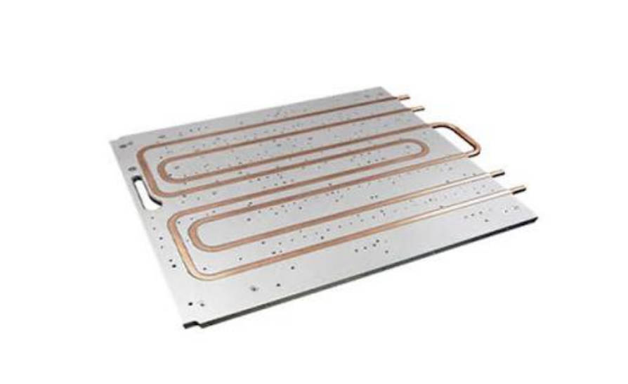
- Tube-embedded designs
- Drilled channel structures
No process is automatically correct for every ESS.
Repeated channel geometry
A repeated internal profile may favor a manufacturing approach that can reproduce the same channels efficiently across volume production.
Complex internal distribution
A plate requiring multiple flow zones or internal heat-transfer structures may require a manufacturing route capable of forming and sealing more complex internal geometry.
Simple high-integrity channels
A simpler fluid path may not justify a more complicated multi-piece construction.
When evaluating custom liquid cold plate manufacturing, the manufacturing method should follow channel geometry, plate size, pressure requirement, production quantity, and cost target—not the other way around.
The Cooling Plate Should Be Designed for Assembly, Not Just Thermal Simulation
ESS cooling plates are installed into a larger mechanical system.
A successful thermal model can still become difficult to manufacture or assemble if the design ignores:
- Module mounting points
- Rack structure
- Coolant-port access
- Hose routing
- Manifold clearance
- Electrical insulation requirements
- Service access
- Plate weight
- Installation sequence
Ports deserve particular attention.
A theoretically convenient inlet position may become impractical once:
- Battery modules
- Busbars
- Harnesses
- Enclosure walls
- Manifolds
are included in the full assembly.
The plate should therefore be reviewed in the complete ESS 3D model before the design is frozen.
A Battery Cooling Prototype Should Answer Six Different Questions
Prototype testing becomes more useful when the team separates different performance layers.
1. Contact
Does the plate contact the battery module correctly?
2. Temperature Uniformity
Are the major battery zones maintained within the project’s allowable temperature distribution?
3. Hydraulic Performance
What flow rate and pressure drop occur at the intended operating condition?
4. Sealing
Does the plate remain fluid-tight under the project’s defined validation conditions?
5. Mechanical Integration
Do ports, mounting points, interfaces, and surrounding parts fit the actual ESS assembly?
6. Rack-Level Distribution
When several plates operate together, do all branches receive appropriate coolant flow?
A plate can pass the first five tests individually and still reveal a problem when multiple units are connected to the same manifold.
This is why component validation and system validation are different tasks.
Four ESS Cooling Problems That Should Not Be Solved by Adding More Flow
When thermal performance is insufficient, increasing pump flow is tempting.
But first diagnose the problem.
Problem: One side of the module remains warm
Possible issue: contact or channel distribution.
More total flow may not fix local flow imbalance.
Problem: Every module is warmer than expected
Possible issue: coolant inlet temperature or overall heat-rejection capacity.
Changing the cold plate alone may not solve it.
Problem: First rack branches are cool, later branches are warmer
Possible issue: manifold or branch distribution.
The system-level hydraulic architecture needs review.
Problem: Pressure drop is already high
Increasing flow can make the hydraulic problem worse.
The channel geometry may need simplification.
These examples illustrate why ESS cooling optimization should be diagnostic rather than simply increasing pump capacity.
Prepare an ESS Cooling Design Package Before Requesting a Quote
A useful inquiry to a liquid cold plate manufacturer should describe both the battery and the coolant system.
Battery Module Information
- Module dimensions
- Number of modules
- Module arrangement
- Heat generation under relevant operating conditions
- Contact surface
- Maximum operating temperature
- Temperature-uniformity requirement
Operating Profile
- Charging condition
- Discharging condition
- Typical continuous operation
- Peak operating condition
- Environmental temperature range
Cold Plate Envelope
- Maximum length
- Width
- Thickness
- Mounting positions
- Contact areas
- Port restrictions
- Weight constraints
Coolant System
- Coolant type
- Inlet temperature
- Target flow rate
- Maximum allowable pressure drop
- Operating pressure
- Supply/return architecture
- Pump or manifold information if available
Production Requirements
- Prototype quantity
- Expected production volume
- Material requirement
- Surface treatment
- Validation requirement
- Inspection requirement
A useful ESS cooling RFQ describes the battery thermal target and complete coolant-loop boundary conditions, not simply the dimensions of an existing cooling plate.
That information allows the manufacturer to evaluate whether the requested internal channel is appropriate before manufacturing begins.
Project drawings and thermal requirements can be submitted through Jindu Tech for custom cold plate evaluation.
Final Design Principle: Optimize the Rack, Not Just the Plate
An energy storage liquid cooling plate performs one local function inside a much larger thermal system.
A plate can have:
- Excellent thermal resistance
- Uniform internal channels
- Strong sealing
and the ESS can still experience uneven battery temperatures if the rack manifold distributes coolant poorly.
Likewise, a well-balanced manifold cannot compensate for inconsistent contact between the modules and cold plates.
The design therefore needs to work at three levels:
Module Level
Control contact and local battery temperature.
Cold Plate Level
Balance temperature uniformity, flow rate, and pressure drop.
Rack Level
Distribute coolant consistently between multiple battery modules.
The strongest ESS cooling architecture is the one in which all three levels support each other.
For energy storage systems, a successful liquid cooling plate is not simply the plate that removes the most heat—it is the plate that supports stable, uniform, and hydraulically practical cooling across the complete battery system.
FAQ
Why do energy storage systems use liquid cooling plates?
Liquid cooling plates transfer heat from battery modules into circulating coolant, allowing heat to be transported to another part of the ESS thermal system. They are particularly useful when battery density, enclosure space, or temperature-uniformity requirements make conventional air cooling more difficult.
Why is temperature uniformity important in ESS battery cooling?
An ESS contains many cells and modules operating together. Large temperature differences can expose different parts of the battery system to different thermal conditions. A well-designed battery cooling plate therefore aims to control both maximum temperature and temperature distribution across the module or rack.
How should coolant channels be designed for a battery cooling plate?
Channel design should follow battery heat distribution, contact area, available flow, and pressure-drop limits. Parallel, serpentine, or zoned channels can all be appropriate depending on the module. The goal is sufficient local heat transfer and temperature uniformity without unnecessary hydraulic resistance.
Does higher coolant flow always improve an ESS cooling system?
Higher flow can improve heat transfer, but it also increases pressure drop and pump demand. If poor cooling is caused by contact resistance, branch imbalance, or channel distribution, simply increasing total flow may provide limited improvement. Flow rate should be optimized together with temperature and hydraulic performance.
How are multiple liquid cooling plates connected in an energy storage rack?
Multiple plates can connect to supply and return manifolds through separate branches. The hydraulic resistance of each branch should be considered so modules receive appropriate flow. Total system flow alone is not sufficient to confirm that coolant distribution is balanced across the complete rack.
What manufacturing process is used for an energy storage liquid cooling plate?
The process depends on channel complexity, plate dimensions, material, pressure requirement, volume, and cost. Possible structures include extruded channels, machined-and-joined plates, friction-stir-welded designs, vacuum-brazed structures, drilled channels, and tube-embedded cooling plates.
What should I send to a liquid cold plate manufacturer for an ESS project?
Provide battery module dimensions, module quantity, heat generation, contact surfaces, temperature targets, cooling plate envelope, coolant type, inlet temperature, target flow rate, pressure-drop limit, operating pressure, port positions, manifold information, prototype quantity, and expected production requirements.