High-Density Zipper Fin Heat Sinks: Precision Engineering for High-Power Cooling
首页 » Zipper Fin Heat Sinks
What is a Zipper Fin Heat Sink?
A Zipper Fin Heat Sink is a high-performance thermal management component where independent metal fins are assembled into a dense array and secured to a base plate using mechanical interlocking or specialized bonding.
Individual fins are stamped with interlocking “teeth” that snap together like a zipper. This modular design allows Jindu to bypass the aspect-ratio limitations of traditional extrusion, achieving a significantly higher Fins Per Inch (FPI) and maximizing the convective surface area in compact footprints.
Why Choose Zipper Fin Technology for Your Thermal Project?
- Unrivaled Fin Density (High FPI)
Achieve cooling surface areas that are impossible with standard extrusion. Thinner fins (starting at 0.2mm) can be packed tightly to maximize heat dissipation in airflow-limited environments.
- Hybrid Material Capability
Solve thermal bottlenecks by mixing materials. Jindu can combine lightweight aluminum fins with high-conductivity copper base plates to ensure rapid heat transfer where it matters most.
- Extended Aspect Ratios
Unlike extruded fins that are limited by die strength, zipper fins can reach heights up to 50mm while maintaining structural stability and uniform spacing.
- Lightweight Structural Rigidity
The mechanical interlocking teeth create a self-supporting fin stack that is incredibly rigid yet remains lighter than solid skived or cast alternatives.
Jindu’s Core Technology: Crimped vs. Staked Fins
To meet diverse application requirements, Jindu offers two primary structural configurations

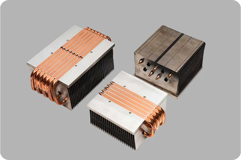
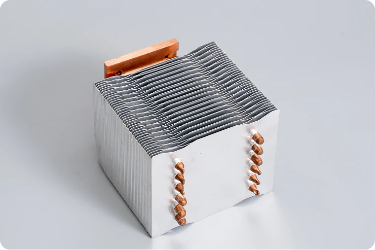
Crimped / Snap-Fit Fin Process
● The Mechanism: Fins feature a specialized hook-like root that is mechanically pressed into precision-machined grooves in the base plate.
● Technical Advantage: No soldering or thermal adhesives are required. It relies on a high-pressure interference fit (0.05-0.15mm), making it an eco-friendly and cost-effective solution for high-volume production.
● Best For: Applications under 100W where cost-efficiency and rapid assembly are critical.

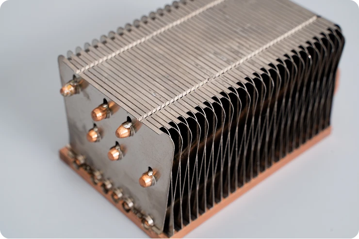
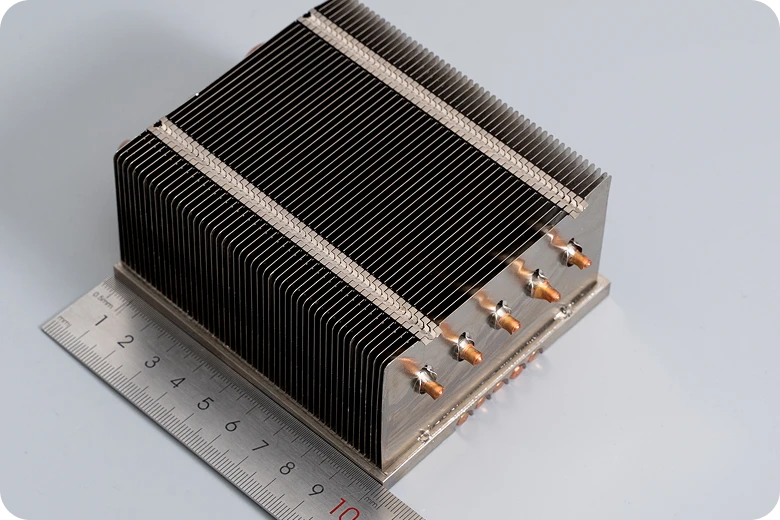
Staked / Inserted Fin Process
● The Mechanism: Fins are inserted through the base plate and permanently bonded via soldering, thermal epoxy, or mechanical expansion.
● Technical Advantage: Offers superior joint strength (≥50N/tooth) and the lowest possible contact thermal resistance.
● Best For: High-power systems (>100W) and harsh environments (automotive, aerospace) prone to high vibration or thermal shock.
Technical Performance Specifications
As an IATF 16949 certified manufacturer, Jindu maintains the following technical standards
| Key Parameter | Crimped Fin Solution | Staked Fin Solution |
| Max Fin Height | ≤ 30mm | ≤ 50mm |
| Pull-out Strength | 20 – 40N / tooth | 50 – 100N / tooth |
| Contact Thermal Resistance | 0.2 – 0.5 ℃/W 0.2 – 0.5 °C/W | 0.1 – 0.3 ℃/W 0.1 – 0.3 °C/W |
| Manufacturing Tolerance | ± 0.02mm | ± 0.005mm (CNC Base) |
| Typical Daily Capacity | 800 – 1200 units | 300 – 600 units |
FAQ Section: Technical Insights
Zipper fins generally outperform extrusions in high-heat-flux applications. Because we can pack more fins into the same volume (higher FPI), the available cooling surface area is significantly larger. This allows for superior performance in forced-air cooling systems where space is constrained.
Yes. We specialize in "Bi-Metal" solutions. We often use a copper base plate for rapid heat spreading from the component, paired with aluminum zipper fins to reduce overall weight and cost.
Unlike extrusion which is limited by die breakage, zipper fins allow for much higher ratios. Depending on the airflow requirements, we can achieve fin heights up to 50mm with precise spacing as narrow as 1.0mm.
For high-vibration applications (such as automotive or industrial machinery), we recommend our Staked Fin process. By using soldering or high-strength thermal epoxy, we achieve a pull-out force of up to 100N per tooth, ensuring the assembly remains thermally and mechanically stable.
Absolutely. Our engineering team utilizes Finite Element Analysis (FEA) to simulate thermal loads, air pressure drop, and structural stress. This ensures the design is optimized for your specific environment before we move to tooling and production.