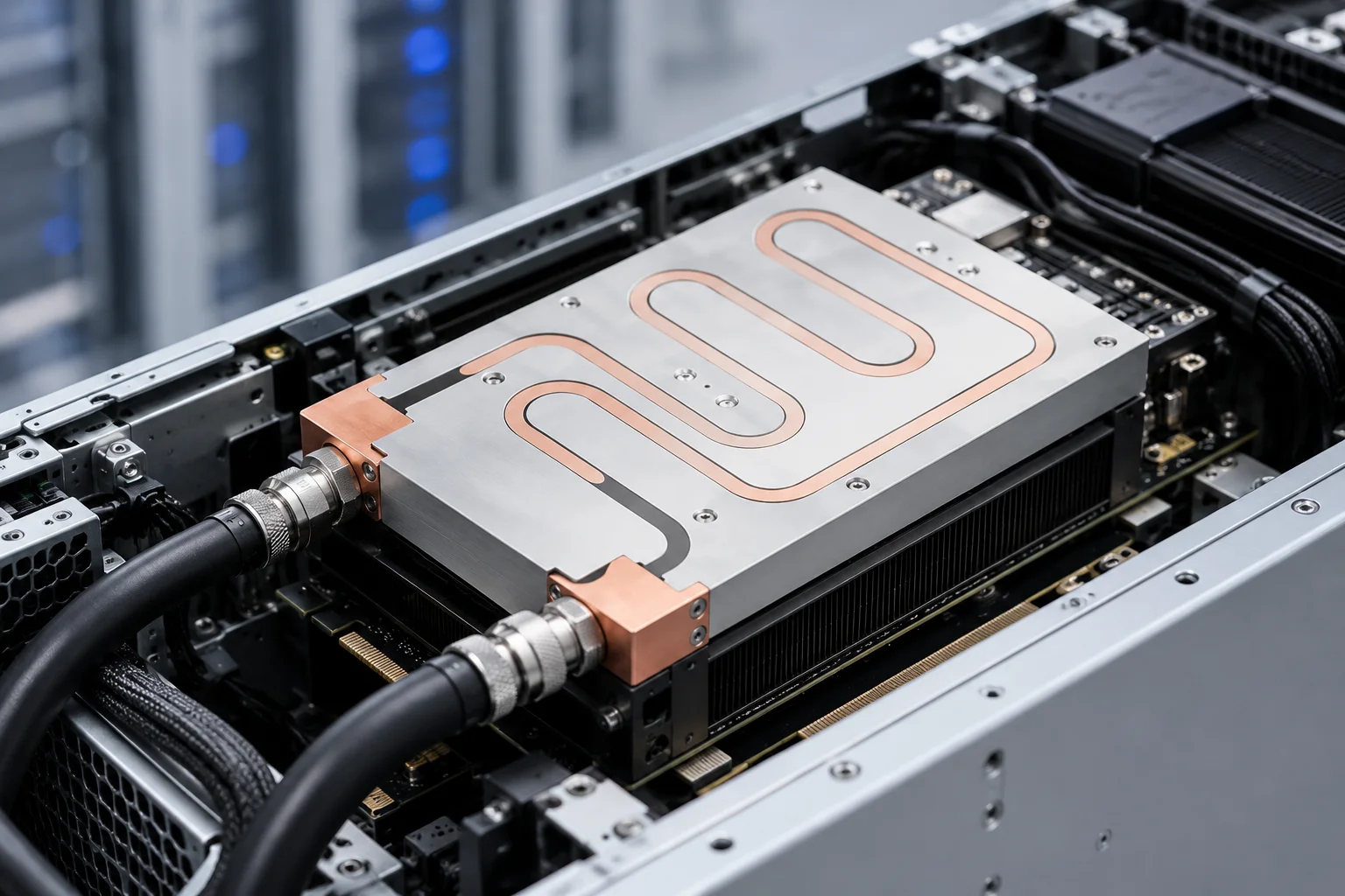
You install a copper heat sink, and the chip still throttles or hits its temperature wall. The problem is often not how much faster copper conducts heat than aluminum. It is what happens in the few millimeters after heat leaves the die: spreading resistance concentrates the hot spot directly under the chip, air gaps and oxide layers quietly add thermal resistance, and the flatness specified on the drawing quietly relaxes in production. Copper’s thermal conductivity is about 390–400 W/m·K, aluminum’s is about 200 W/m·K, copper density is about 8.9 g/cm³, and aluminum density is about 2.7 g/cm³. These numbers are a starting point, not a conclusion.
In PTSMAKE’s thermal management projects, we rarely see copper heat sinks fail because the copper was not pure enough. We see them fail because the material grade did not match the operating conditions, the interface specification never made it onto the drawing, or the geometry fought the airflow direction. This guide follows a buyer’s decision chain: why copper works and where it loses performance, how to turn “copper” into purchasable grades and inspectable interface specs, where copper’s limits are, when aluminum is the better choice, how manufacturing constrains the design, how geometry must match airflow, and finally how to specify and verify a copper heat sink with a supplier.
1. Why Copper Heat Sinks Work: Thermal Conductivity and Spreading Resistance
1.1 Copper vs Aluminum Thermal Conductivity in Real Heat Sink Designs
Copper’s first advantage shows up in spreading resistance. When the heat source is much smaller than the heat sink base, a copper heat sink typically has about half the spreading resistance of an aluminum heat sink, because copper’s thermal conductivity is roughly twice as high. Selection guidance from QATS makes the same point: when the component footprint is much smaller than the heat sink base, copper can significantly reduce spreading resistance. (If you’re still evaluating materials, read our full breakdown on copper vs aluminum skived heat sink design.)
But thermal conductivity is not the whole module-level thermal resistance. In natural convection or low-airflow conditions, copper fins move heat away from the base quickly, yet the fins’ ability to reject heat to air depends on surface area, fin efficiency, and airflow together. If fin spacing is too tight and airflow is insufficient, copper fins simply accumulate heat faster instead of dissipating it into the environment. Copper absorbs heat quickly but rejects it relatively slowly, which means full-copper fins often need higher airflow to realize the bulk conductivity advantage.
1.2 Spreading Resistance: The Hidden Bottleneck Under a Small Heat Source
A chip die is often on the order of 10 × 10 mm, while the heat sink base may be 40 × 40 mm or larger. If the base cannot conduct heat laterally well enough, heat never spreads to the outer fins, a hot spot forms in the center, and the outer fins are effectively idling. Copper’s value is that it turns a point heat source into an area heat source quickly, bringing more fin area into useful operation.
A simple analogy: an aluminum base is like a road with traffic lights, where heat cannot travel far laterally before being forced upward. A copper base is like a wider, smoother highway, where heat spreads laterally first and then hands off to the fins evenly. But a highway still needs exits. If airflow or surface area on the fin side is insufficient, the laterally spread heat still backs up on the fins.
1.3 When a Copper Base Makes More Sense Than a Full Copper Heat Sink
Not every application justifies full copper. When heat flux is concentrated on a small die and the installation space and weight budget allow, a copper base with aluminum fins is often more practical than an all-copper design: the copper base spreads the hot spot, and the aluminum fins provide heat transfer area at lower weight and cost. Full copper suits extremely high heat flux, very tight spaces, or cases where aluminum fin efficiency cannot carry the heat away. All-aluminum remains a reasonable first choice when weight and cost constraints dominate.
| Design | Heat Distribution | Weight | Cost | Fin Utilization | Typical Use |
|---|---|---|---|---|---|
| Full copper | Most uniform, lowest spreading resistance | Highest | Highest | High, but depends on airflow to deliver | Very high heat flux, sealed enclosures, tight space |
| Copper base + aluminum fins | Good base spreading, moderate fin efficiency | Medium | Medium | Depends on copper thickness and interface | Most air-cooled servers, power supplies, industrial modules |
| All aluminum | More concentrated hot spot, higher spreading resistance | Lowest | Lowest | Acceptable with sufficient airflow and fin area | Consumer electronics, natural convection, weight-sensitive designs |
2. Copper Purity and Alloy Grades: C10100 vs C11000 and What Actually Matters
2.1 C10100 OFE Copper: Higher Purity, Lower Oxygen, Better Hydrogen Resistance
C10100 is oxygen-free high-conductivity (OFHC) copper with oxygen content below 0.0005%, purity of at least 99.99%, thermal conductivity around 391 W/m·K, and IACS around 101%. Its core value is not the roughly 1% thermal conductivity advantage over C11000—C11000 is about 388 W/m·K, a practically negligible difference—but its near-zero oxygen content, which eliminates hydrogen embrittlement risk at the root.
When a part must be brazed in a hydrogen-containing reducing atmosphere or serves long-term under high-temperature vacuum, C10100 is one of the few copper grades that can be used safely. Oxygen in C11000 exists as Cu₂O particles; in a reducing atmosphere, oxygen reacts with hydrogen to form water vapor, creating high-pressure bubbles at grain boundaries and embrittling the material. This is permanent failure, not a slight performance drop.
2.2 C11000 ETP Copper: The Industry Standard for Most Heat Sinks
C11000 is electrolytic tough pitch (ETP) copper with 0.02–0.04% oxygen and thermal conductivity around 388 W/m·K. Its mechanical properties are nearly identical to C10100 before thermal exposure, and its IACS is about 100%. Its advantages are cost, machinability, and supply stability. For the vast majority of air-cooled copper heat sinks—no hydrogen brazing, no high-temperature vacuum service—C11000 is the default choice. Specifying C10100 instead brings no perceptible thermal benefit but increases material cost noticeably. (As a reference, our CNC machining capabilities regularly work with C1100 pure copper for thermal components.)
2.3 Does Higher Copper Purity Always Improve Heat Sink Performance?
Not necessarily. When heat flux is moderate and the bottleneck is spreading resistance or interface resistance, C10100’s marginal conductivity advantage over C11000 is drowned out by geometry and interface. The cost of over-specifying C10100 is real: material premium plus narrower supply channels can raise piece cost by 30%–80%, while the module-level θ improvement may sit within measurement error.
Conversely, using C11000 where C10100 is genuinely required is not “slightly less efficient”—it is catastrophic failure after brazing or high-temperature service. Grade selection should be driven by manufacturing process and service environment, not by the intuition that “higher purity is always better.”
| Grade | Purity | Oxygen | Thermal Conductivity | Hydrogen Embrittlement Risk | Best Use |
|---|---|---|---|---|---|
| C10100 (OFHC) | ≥99.99% | <0.0005% | ~391 W/m·K | Immune | Hydrogen brazing, high-temperature vacuum, extreme reliability |
| C11000 (ETP) | ≥99.9% | 0.02–0.04% (Cu₂O) | ~388 W/m·K | Sensitive in reducing atmospheres | Most air-cooled heat sinks, CNC-machined parts |
3. Surface Finish, Flatness, and TIM: Where Copper Heat Sinks Lose Performance
3.1 Why Air Gaps Matter More Than Copper Conductivity
A copper heat sink that passes CAD and looks clean in CFD can still run 8–25°C above the junction temperature limit on the first prototype. The most common cause is not copper’s bulk conductivity but interface resistance: the module-level contact interface can contribute 0.05–0.30 K/W, enough to wipe out the benefit of a heat sink redesign. Air’s thermal conductivity is only about 0.026 W/m·K, versus about 390 W/m·K for copper. When two visually “flat” metal surfaces mate, the real contact area—without sufficient pressure and surface engineering—is typically only a small fraction of the apparent area, and the remaining gaps are filled with air, becoming a thermal bottleneck.
Interface resistance is not just “there is a layer of TIM between copper and chip.” TIM is often one of the highest-resistance constituents in the whole package, and what is truly fatal is uncontrolled bond line thickness (BLT): the rougher the surface, the thicker the TIM must be to fill the gaps, and thermal resistance rises linearly with BLT. Commercial TIMs can achieve minimum BLT on the order of 50 μm, but if base flatness is insufficient, actual BLT can be several times that number.
3.2 Milling, Grinding, and Lapping: Flatness Grades and TIM Thickness
Different machining methods deliver different flatness and roughness capabilities. Standard milling can satisfy general heat sink mounting surfaces, but when heat flux rises and TIM must be pressed very thin, precision grinding and lapping/polishing earn their keep. Industry reference values serve as specification anchors: flatness within 50 μm over a 100 mm span and mounting-surface roughness Ra below 10 μm are common targets, while higher-end copper vapor chambers can reach flatness below 0.05 mm, with bonding-surface Ra above 2.0 μm and cosmetic-surface Ra of 0.2–0.6 μm.
An easily overlooked failure mode is local hot spots caused by uneven mounting pressure. Tightening one screw first, inconsistent spring pressure, or substrate warpage concentrates contact pressure locally and spikes interface resistance elsewhere. The die region over the low-pressure zone becomes a hot spot while the heat sink as a whole looks “not that hot.” The drawing must specify not only flatness and Ra but also mounting pressure range, tightening sequence, and a sampling method to verify interface resistance after assembly. (For reference, our die-cast and CNC finishing processes achieve surface roughness Ra ≤0.8μm and mounting flatness ≤0.1mm/100mm.)
3.3 How to Specify Flatness and Surface Finish on a Copper Heat Sink Drawing
Procurement and engineering should lock down inspectable specifications on the drawing, not adjectives like “precision machined.” An executable interface specification includes at least: mounting-surface flatness value and measurement span, surface roughness Ra upper limit, TIM type and target BLT range, mounting pressure or fastening torque range, and flatness inspection method plus sampling frequency. If the heat sink has a bonded copper-to-aluminum interface, the void rate limit for that interface must also be specified separately.
PTSMAKE’s precision machining capabilities cover these flatness and roughness grades, including ground and lapped mounting surfaces for thin-BLT assemblies and void-rate control for brazed or bonded interfaces. This means the interface specification can be written around what the process can actually hold, rather than around a generic “precision machined” claim that no incoming inspection can verify.
One diagnostic clue is worth remembering: the copper heat sink feels hot to the touch, yet the chip still throttles or hits the temperature wall. This usually means die-to-base ΔT is too large; check flatness, mounting pressure, oxide layer, and TIM coverage before switching to more expensive copper or adding fin area.
4. The Limits of Copper: Weight, Cost, and Mechanical Constraints
4.1 Copper Density and Its Impact on PCB and Mounting Design
Copper density is about 8.9 g/cm³, roughly 3.3 times that of aluminum. A full-copper heat sink that performs beautifully on the bench can impose extra mechanical burden on the PCB: board bow, screw-hole pull-out, and inertial loads under drop or vibration all need to be accounted for at the structural design stage. For large bases or tall full-copper fins, the weight is not just “heavy to lift”—it changes PCB modes and solder-joint stress.
4.2 Cost Drivers: Raw Material, Machining, and Surface Treatment
The cost gap between copper and aluminum heat sinks is far larger than the raw material price gap. Aluminum raw material is roughly in the $2–4/kg range, copper in the $8–12/kg range; but finished copper heat sinks often cost several times more than equivalent aluminum parts because copper wears tools faster, requires more conservative cutting parameters, and adds surface treatment steps such as nickel plating. For equal usage, copper material cost can be several to more than ten times that of aluminum, depending on the day’s metal prices and geometric complexity.
The rational way to use copper is not “copper wherever possible” but placing copper where heat flux is highest and spreading resistance hurts most, letting aluminum carry the heat-transfer area that is sensitive to weight and cost.
4.3 Oxidation and Corrosion: When Copper Needs a Coating
Bare copper oxidizes in air, and copper oxide significantly degrades thermal conductivity while causing appearance discoloration and long-term performance drift. Electroless nickel coating is thin, and its impact on initial thermal resistance is usually limited because the nickel layer is on the micrometer scale, even though nickel’s thermal conductivity is far below copper’s. What truly warrants caution is local oxidation after coating damage: once the nickel layer is scratched or worn, exposed copper begins to oxidize, the oxide becomes an interface barrier, and thermal performance degrades over long-term service.
Coating decisions therefore involve not only the initial thermal-resistance trade-off of “nickel or not” but also wear, corrosion, and long-term reliability in the service environment. In clean, dry, wear-free indoor environments, bare copper or passivation may suffice; in humid, sulfur-containing, or friction-prone scenarios involving repeated insertion, nickel coating or a more corrosion-resistant surface treatment is the reasonable choice.
5. Copper vs Aluminum Heat Sink: When Aluminum Is the Better Choice
5.1 Performance per Weight and Performance per Cost
Copper’s thermal conductivity is about twice aluminum’s, but its density is 3.3 times higher. This means that for the same weight, aluminum can be made thicker, with more fins and larger surface area; for the same cost, aluminum’s volume advantage is even more pronounced. The top-voted answer on Stack Exchange makes exactly this point: pure copper’s conductivity advantage is real but not free; under weight or cost constraints, aluminum can compensate for lower material conductivity with larger heat-transfer area.
When natural convection or low airflow dominates, surface area and fin spacing often determine module-level performance more than bulk conductivity. In such cases, all-aluminum or copper-base-aluminum-fin designs may outperform full copper at the system level.
5.2 Applications Where Aluminum Wins: Aerospace, Portable Devices, High-Volume Electronics
In weight-sensitive applications—drones, portable devices, mobile robots, aerospace—aluminum’s density advantage is decisive. In cost-sensitive high-volume consumer electronics, copper struggles to displace aluminum on raw material and machining economics. In these scenarios, unless heat flux is already high enough that spreading resistance becomes an insurmountable bottleneck, aluminum is usually the more reasonable first choice.
5.3 Hybrid Designs: Copper Base with Aluminum Fins
The intent of a hybrid design is to put copper where lateral spreading is most needed (the base) and aluminum where large-area heat rejection is needed (the fins). But hybrid structures are not a free lunch: copper-aluminum joints are prone to pores, impurities, and interface thermal resistance, and conventional welding or copper-plug joining can reduce thermal conduction efficiency. The interface resistance of copper-aluminum composites can reduce overall thermal conductivity by 30%–50%, depending on joining process and interface quality.
When choosing a copper-base-aluminum-fin design, the joining process and interface quality control matter as much as the “copper ratio.” An unreliable copper-aluminum interface will eat the copper base’s advantage, while a validated brazing, diffusion bonding, or mechanical interlock structure is what actually delivers the “copper spreads, aluminum rejects” logic.
| Constraint / Condition | Recommended Design | Why |
|---|---|---|
| High heat flux on a very small die | Copper base + aluminum fins, or full copper | Spreading resistance dominates; copper is needed where it spreads heat |
| Tight weight budget (drones, portable devices) | All aluminum, or thin copper base + aluminum fins | Copper’s density penalty outweighs its conductivity gain |
| Cost-sensitive high volume | All aluminum, or minimal copper base | Material and machining economics favor aluminum |
| Natural convection, low airflow | All aluminum with wider fin spacing, or copper base + aluminum fins | Surface area and fin spacing matter more than bulk conductivity |
| Sealed enclosure, very high heat flux | Full copper | Both spreading and fin efficiency are needed |
| Harsh or corrosive environment | Nickel-coated copper base + aluminum fins | Coating must cover both the copper and the joining interface |
6. How Copper Heat Sinks Are Manufactured: Skiving, Forging, CNC, and Bonding
6.1 Skived Copper Heat Sinks: High Fin Density and Material Efficiency

Skiving cuts thin fins from a solid block of metal, so the fins and base are one continuous material with no adhesive layer, braze layer, or solder line. This means there is no interface thermal resistance between fin and base; heat travels from base to fin through a single metal path. Skiving can achieve fin thickness of 0.2–0.5 mm, spacing on the order of 0.5 mm, and aspect ratios above 40:1 or even 50:1, suiting compact, high-heat-flux applications.
But skiving’s inherent costs must be designed in: the base is usually thicker, and the very thin fins are fragile and easily damaged in shipping and assembly. For copper, tool wear is faster than for aluminum, and unit cost rises with fin density and aspect ratio in production. If the drawing’s fin spacing exceeds the physical limits of the stock and tooling, the lab prototype may pass while production cost spirals.
6.2 Forged and Die-Cast Copper: When It Makes Sense
Copper forging and die casting face greater challenges than aluminum in die life, high-temperature flowability, and piece cost. Forged copper can provide good rigidity and near-net shape, but the high-tonnage tooling investment means it suits projects with clear volumes and relatively stable geometry. For copper heat sinks with very high heat flux and complex three-dimensional geometry, forging or casting may be a reasonable route, but tooling cost and yield risk must carry the same decision weight as thermal performance.
6.3 CNC Machining and Bonded Fin Assemblies
CNC machining suits prototypes, low volumes, and complex base features—mounting holes, steps, and copper insert structures can all be completed in a single setup. For fin densities beyond skiving or forging capability, bonded fin (adhesive or brazed fins) expands geometric freedom, but the bond layer between fin and base directly adds total thermal resistance, and voids and aging in that layer are long-term reliability risks. When maximum module-level performance is required, monolithic skived or forged structures usually beat bonded ones; bonded designs make sense when geometric complexity or volume cost dominates.
6.4 Manufacturing Process Selection Table
| Process | Typical Min Fin Thickness | Fin/Base Interface | Geometric Freedom | Cost Profile | Best Application |
|---|---|---|---|---|---|
| Skiving | 0.2–0.5 mm | Monolithic, no interface | High fin density, mostly 2D | Tool wear rises with density | High heat flux, compact space, volume |
| Forging | Thicker | Monolithic | 3D near-net shape | High tooling, volume-sensitive | Complex geometry, rigidity priority |
| CNC | Tool-limited | Monolithic or assembled | Most flexible base features | Economical for one-offs/low volume | Prototypes, low volume, complex mounting faces |
| Bonded fin | Can be very thin | Adhesive/braze layer | High | Bond layer adds resistance and reliability risk | Geometric freedom over ultimate thermal performance |
PTSMAKE’s process coverage includes skived copper heat sinks, CNC-machined base features, and bonded fin assemblies, so this process selection table can be evaluated against both thermal design and manufacturing constraints rather than treated as a post-design purchasing decision.
7. Choosing the Right Copper Heat Sink Geometry: Fin Type, Airflow, and Orientation
7.1 Plate Fin vs Pin Fin vs Flared Fin
Straight (plate) fins are the most direct and effective choice in forced air with a clear airflow direction and limited pressure-drop budget. Pin fins provide more uniform heat transfer in omni-directional airflow or natural convection, but pressure drop and machining cost are usually higher. Flared fins improve airflow distribution through fin-end expansion and suit specific low-airflow or natural-convection scenarios. QATS’s selection guidance lists pin fin, straight fin, and flared fin as the most common air-cooling geometries, with the choice driven by airflow pattern, pressure-drop constraints, and mounting orientation—not by “which fin type has the highest efficiency.”
7.2 Matching Fin Density to Airflow
Higher fin density does not automatically mean better heat transfer. The tighter the fin spacing, the more easily boundary layers overlap between adjacent fins, and the air is heated and slowed before reaching the fin base. In low airflow or natural convection, overly dense fins increase pressure drop and reduce mass flow, and actual heat transfer can degrade. Skived copper can achieve very high fin density, but that only matters when airflow can penetrate the fin channels; in a sealed, weak-airflow enclosure, moderate density with wider spacing is often more reliable than a “lab-optimal” high-density design.
7.3 Orientation and Gravity in Natural Convection
In natural convection, mounting orientation can significantly change performance. Published data show pin-fin arrays typically perform best facing up (0°), with vertical orientation (90°) about 15% lower in heat transfer coefficient and fully downward (180°) about 20% lower. For straight-fin heat sinks, deviation from the optimal mounting angle can also reduce cooling capacity by roughly 7%–15%, and pin fins can show 20%–40% performance degradation at a 60° tilt.
For fanless or low-airflow copper heat sinks, the wrong orientation can directly determine whether the device overheats. Fin channel direction should align with the developing natural-convection boundary layer, not with what makes the enclosure “look good.” Assessing mounting orientation, gravity direction, and surrounding obstructions at the selection stage is far cheaper than discovering throttling on a prototype and then changing the structure.
8. A Practical Copper Heat Sink Selection Checklist
8.1 Thermal Requirements Checklist
Lock down the thermal parameters before discussing materials. You need to define: the chip’s continuous and peak power, allowable junction and case temperatures, maximum ambient temperature, hot-spot size (die or heat-source area), and airflow conditions (natural convection, velocity, direction). Hot-spot size is especially critical: if the source area is much smaller than the base, spreading resistance is unavoidable, and the benefit of a copper base or full copper must be evaluated on that term; if the source area is already close to the base, copper’s lateral-spreading advantage shrinks.
8.2 Mechanical and Manufacturing Checklist
Mechanical constraints must be locked before the drawing is released: weight limit, PCB mounting method and support structure, fastening torque or mounting pressure range, flatness and Ra specification, TIM type and target BLT, surface treatment (bare copper, passivation, nickel plating), and volume-appropriate process choice (skiving, CNC, forging, or bonded fin). If a hybrid structure is selected, the copper-aluminum joining process and interface void-rate limit must be listed as separate specifications.
8.3 Supplier Evaluation Checklist
If a supplier’s datasheet only says “copper ~390 W/m·K” without module-level thermal resistance or test boundary conditions, it cannot be used to compare how different designs perform under real interface and airflow conditions. When evaluating a supplier, confirm at minimum: material grade certificate (C10100 or C11000), measured flatness and roughness reports with measurement method, TIM BLT control capability, first-article thermal-resistance test data (including test conditions and mounting pressure), and lot-to-lot consistency data. If the supplier cannot provide the boundary conditions of the thermal-resistance test, the θ number itself is unverifiable.
8.4 Turning the Checklist into a Sourcing Decision
Selecting a copper heat sink is not a binary choice between “copper” and “aluminum.” It is a decision chain: first confirm whether heat flux and hot-spot size require copper’s spreading capability, then choose C10100 or C11000 based on manufacturing process and service environment, then put flatness, Ra, TIM, and mounting pressure onto the drawing, and finally lock module-level performance with airflow direction and fin geometry.
If you are selecting a copper heat sink for a specific project, provide the heat load, hot-spot size, allowable junction temperature, installation space, airflow conditions, and expected volume. PTSMAKE’s thermal management team can recommend a coordinated combination of material grade, base structure, manufacturing process, and interface specification based on those inputs, and use verifiable thermal-resistance data during the prototype stage to help you determine whether copper is being used in the right place. You can also explore our full range of custom thermal solutions or liquid cold plate assemblies for high-power applications.
9. FAQ: Copper Heat Sink Questions Engineers Actually Ask
Is copper always better than aluminum for heat sinks?
No. Copper’s spreading-resistance advantage is most obvious when the heat source is much smaller than the base. When weight or cost constraints dominate, or when surface area rules in natural convection, aluminum can compensate for the conductivity gap with larger volume and area.
What is the best copper grade for a heat sink?
C11000 is sufficient for most air-cooled copper heat sinks. Only hydrogen brazing, high-temperature vacuum, or extreme-reliability applications require C10100 to eliminate hydrogen embrittlement risk. Over-specifying C10100 adds cost without necessarily improving module-level θ.
Does a copper heat sink need nickel plating?
It depends on the environment. In clean, dry indoor environments, bare copper or passivation may suffice; in humid, sulfur-containing, mechanically worn, or long-idle conditions where oxidation is likely, a thin nickel coating is reasonable. The key risk is local oxidation after coating damage, not the initial thermal resistance of the nickel layer itself.
How thick should a copper heat sink base be?
There is no fixed value. Base thickness must simultaneously satisfy spreading resistance, mounting rigidity, and thread-depth requirements. For small heat sources, a thicker base can reduce spreading resistance, but the benefit diminishes with thickness; for large heat sources, the marginal thermal benefit of extra base thickness is limited, and the weight and cost penalties deserve more attention.
Can copper and aluminum be used together?
Yes. Copper base with aluminum fins is a common hybrid. But copper-aluminum joints are prone to pores, impurities, and added thermal resistance; joining process and interface quality control matter as much as material ratio. Do not assume “copper plus aluminum” is automatically better than all-aluminum or all-copper.
Why is my copper heat sink still overheating?
Suspect the interface and geometry before suspecting the copper itself. Check flatness, whether mounting pressure is uniform, whether TIM BLT is too thick, whether the copper surface has oxidized, and whether fin orientation matches airflow or natural-convection direction. Any one of these can make a copper heat sink with excellent bulk conductivity fail at the module level.