
A cold plate that performs beautifully in CAD is worthless if it cannot be machined, brazed, cleaned, or inspected. Bridging the gap between theoretical cold plate design and production reality is where most programs fail. Whether you are choosing between monolithic CNC and vacuum brazing, or preparing a pilot lot for OCP-oriented qualification, this guide details the exact manufacturing tolerances, DFM failure maps, RFQ input packages, and qualification test parameters you need to transition from prototype to production.
Key Takeaways
- Manufacturing choice controls the achievable geometry, tolerance, cleanliness, and cost. A thermally attractive design that cannot be machined, brazed, cleaned, or inspected is not production-ready.
- Pilot lots usually fail at four nodes: channel geometry, sealing interface, port/thread interface, and validation records. Each has a known root-cause class and a containment action.
- Monolithic vs. brazed decision: if design proof pressure is ≥ 10 bar with pulsation, or localized heat flux is ≥ 100 W/cm², monolithic or FSW should be prioritized over brazed designs.
- Qualification is not a generic checklist. Mechanical, thermal, pressure-drop, leak, corrosion, vibration, and thermal-cycling requirements must come from the target platform specification and the applicable OCP revision.
- When measured results miss the prediction, check as-built dimensions, surface roughness, port/manifold restrictions, TIM bond line, and local flow starvation before changing the design.
1. CFD and Simulation for Cold Plate Design
1.1 Why Traditional CAD-and-CFD Iteration Can Be Slow
A conventional workflow changes CAD parameters, rebuilds geometry, repairs import errors, generates a mesh, runs a conjugate heat-transfer solver, checks convergence, and reviews results. For a cold plate with internal manifolds, fins, and a cover joint, geometry cleanup and meshing alone can take one to three working days. A single steady-state conjugate solve for a detailed plate commonly takes hours to a day on a workstation. A 20-point parameter sweep therefore becomes a multi-week activity before any prototype is built.
The bottleneck is not the solver alone. It is the repeated geometry-to-mesh-to-result loop, the manual interpretation of each result, and the difficulty of comparing designs when several variables change at once. Parameterized geometry, automated meshing, design-of-experiments methods, and optimization algorithms reduce the repetitive work, but they still depend on a correctly defined objective and a validated baseline model.
Define the objective explicitly: for example, minimize maximum component temperature subject to a pressure-drop limit, a mass limit, a minimum channel width, and a manufacturing process constraint. Without those constraints, optimization will find geometries that cannot be produced or cleaned.
1.2 CFD Boundary Conditions and Validation
A cold plate CFD model may require:
- A heat-generation value or measured heat-flux map on the component interface.
- Coolant inlet temperature and a specified flow rate, mass flow, or suitable pressure boundary conditions.
- Outlet pressure or a representation of the connected hydraulic system.
- Temperature-dependent coolant properties when relevant.
- Solid material properties and conjugate heat transfer between the plate and coolant.
- TIM or contact resistance when interface temperature is part of the objective.
- Appropriate laminar or turbulence treatment, wall resolution, mesh-independence checks, and convergence criteria.
Validate the model by comparing predicted and measured inlet and outlet temperatures, pressure drop, flow rate, and surface temperatures. Document sensor placement and measurement uncertainty. Agreement in one metric does not automatically validate every local flow prediction.
1.3 Topology Optimization, TPMS, Lattices, and Hotspot-Aligned Channels
Topology optimization searches for material or flow-path arrangements that satisfy defined objectives and constraints. TPMS and lattice structures can create large internal surface areas and distribute coolant through complex volumes.
Hotspot-aligned channels can direct cooling capacity toward regions with greater thermal demand. However, the optimization must include pressure-drop limits, minimum feature sizes, structural strength, cleaning, inspection, joining, and manufacturing constraints.
A thermally attractive geometry may still be unsuitable if it cannot be manufactured consistently or verified.
1.4 AI Surrogate Models
A surrogate model approximates the relationship between design inputs and simulation outputs using data from previous simulations or experiments. Once trained and validated within a defined design space, it can estimate outputs such as maximum temperature or pressure drop much faster than a full CFD run.
What a surrogate model actually buys you: after training on tens to a few hundred high-fidelity samples, a surrogate can screen thousands of candidates in seconds to minutes. It does not replace the high-fidelity runs used to generate its training data, and it is unreliable outside the sampled design space. Use it to rank candidates and guide the next CFD batch, then verify the top designs with full simulation and test.
1.5 Implicit Modeling for Complex Cooling Geometry
Implicit modeling represents geometry through mathematical fields rather than only explicit boundary surfaces. It can simplify the generation of lattices, TPMS structures, and continuously varying internal passages.
The resulting geometry must still meet minimum wall thickness, dimensional tolerance, pressure integrity, surface-finish, cleaning, and inspection requirements. Geometry-generation flexibility does not establish manufacturability by itself.
2. Cold Plate Manufacturing and Design for Manufacturability (DFM)
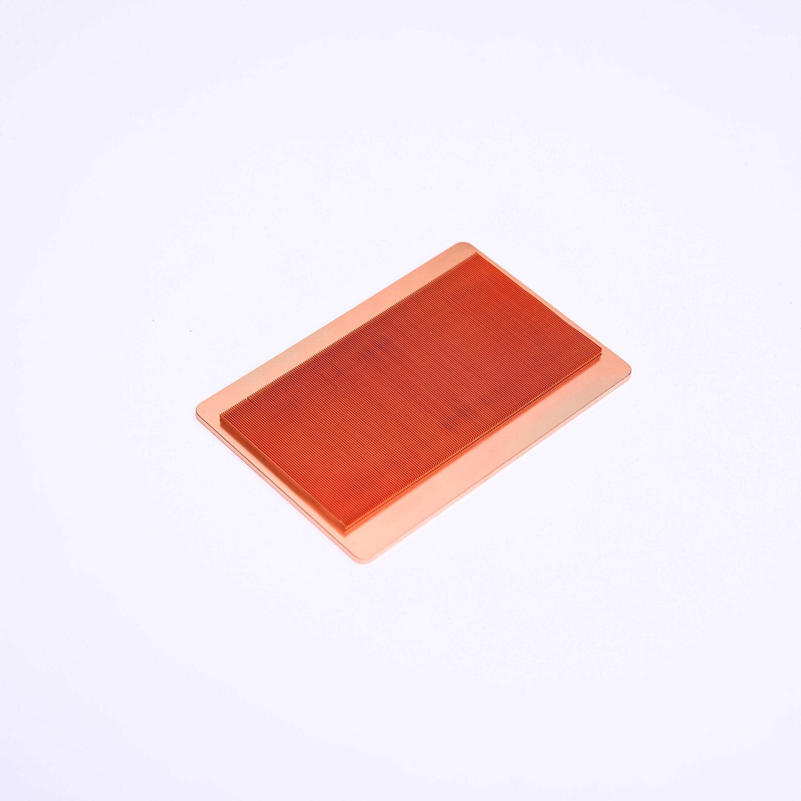
2.1 CNC Machining, Vacuum Brazing, FSW, Stamped, Bonded Fin, and Additive Manufacturing
CNC machining provides control over accessible channels, mounting features, flatness, and sealing surfaces. Deep or enclosed passages may require gun drilling, cross-drilling, plugs, or a separate cover.
Vacuum brazing joins fin stacks and covers into compact assemblies, but joint clearance, process conditions, distortion, and internal cleanliness must be controlled. Narrow channels may be difficult to braze consistently and clean after processing.
Friction stir welding (FSW) can close channels or join covers when joint access, material compatibility, distortion, and inspection requirements are addressed. FSW produces a solid-state joint with low porosity and good mechanical strength, but tool access and distortion control govern feasibility.
Stamped cold plates form channels in thin sheets and join them by brazing or adhesive bonding. They are usually all-aluminum, avoid the copper-aluminum galvanic couple, and are cost-effective at high volume, but the thermal ceiling is lower because the base is thin and the channel geometry is limited by forming.
Bonded-fin cold plates use an adhesive to bond a fin stack to a base and cover. They suit high-density power electronics where a thin, high-fin-density structure is needed. The adhesive’s thermal conductivity and bond-line thickness become part of the thermal-resistance chain, and long-term bond integrity must be qualified.
Additive manufacturing enables complex internal passages and part consolidation. It may require support removal, heat treatment, machining, surface finishing, leak testing, and internal inspection.
The best process depends on geometry, material, performance targets, production volume, and quality requirements.
2.2 Tolerances, Distortion, Sealing Surfaces, and Cleanliness
Cold plates must maintain critical dimensions and sealing features after machining, joining, heat treatment, and operation under pressure. Flatness and surface finish at the component interface affect TIM thickness and contact resistance.
Distortion can alter mounting pressure, interface gaps, and seal compression. Internal debris, burrs, braze residue, loose powder, and machining fluids can obstruct small channels or contaminate the loop.
Define cleaning, flushing, drying, and cleanliness verification procedures. Specify acceptance criteria for critical dimensions, leakage, surface condition, and internal cleanliness. High-precision machining can hold ±0.01 mm on critical features and flatness below 0.02 mm; typical production tolerances are wider. Specify which features require the tight tolerance and which do not, or cost will rise without a thermal benefit.
2.3 Advantages and Limitations of Additively Manufactured Cold Plates
Additive manufacturing is useful when conformal passages, branching networks, lightweight structures, or integrated manifolds offer measurable benefits. It can reduce the number of separate parts in some designs.
Limitations include material and machine cost, build size, surface roughness, dimensional variation, trapped powder, post-processing, and limited access for internal inspection.
Compare total qualified-part cost rather than build cost alone. Include finishing, cleaning, testing, yield, and qualification requirements.
2.4 Prototype Validation and Transition to Production
Prototypes should verify thermal performance, pressure drop, leakage, interfaces, and manufacturing assumptions. Early samples can also reveal assembly-access, port-orientation, sealing, and cleaning issues that are not obvious in CAD.
Before scaling production, establish process controls, inspection plans, traceability, acceptance limits, and change-control procedures. Revalidate when a material, supplier, joining process, channel geometry, or critical tolerance changes.
2.5 Cold Plate Manufacturing Methods Compared
| Method | Typical tolerance / capability | Cost drivers | Best application | Production fit |
|---|---|---|---|---|
| CNC machining (milled channels + cover) | Accessible features typically ±0.05–0.1 mm; high-precision processes can hold ±0.01 mm on critical features and flatness below 0.02 mm; seal surfaces require tighter control | Machine time, tooling, material removal, setup, cover joint | Prototypes and tailored channel layouts | Prototype through low/medium production |
| Gun-drilled | Hole position and straightness typically ±0.1 mm class; depth-to-diameter limits apply; cross-drilled plugs add sealing risk | Deep-hole capability, plug sealing, length | Long, straight internal passages; large-format plates | Medium to high volume for simple straight routes |
| Vacuum brazed fin stack | Joint clearance and fin placement typically controlled to ±0.05–0.1 mm; distortion and braze fillet quality are critical; micro-voids are a known risk and must be inspected | Fixtures, furnace cycle, yield, inspection, cleanliness | Compact, high-surface-area designs | Repeatable batches with qualified process |
| Friction stir welding (FSW) | Joint line and cover flatness typically ±0.1 mm class; distortion and tool access govern feasibility; solid-state joint with low porosity | Joint preparation, fixturing, process development, inspection | Sealed covers and compatible metal assemblies; higher stiffness than brazed joints | When process repeatability is proven |
| Stamped | Forming tolerance and joint flatness govern; tooling amortization requires high volume | Tooling, material, joint yield | High-volume, cost-sensitive, all-aluminum designs | High volume only |
| Bonded fin | Adhesive bond-line thickness and cure process govern; long-term bond integrity must be qualified | Adhesive selection, cure, inspection | High-density power electronics with moderate temperature limits | Medium to high volume with qualified adhesive process |
| Additive manufacturing | Feature size typically 0.2–0.5 mm class depending on process; surface roughness and internal variation require validation; trapped powder is a risk | Build time, material, support removal, finishing, testing | Conformal, branched, lattice, and integrated passages | Complex designs; economics depend on application |
Pressure-drop implication by process: vacuum-brazed fin stacks can reach higher fin density (up to 60–70 fins per inch in high-performance designs) but the narrower channels increase hydraulic resistance; the design must balance channel density against the available pump head. Machined channels offer more direct control over cross-section and are easier to keep at a lower pressure drop for the same channel count, but they cannot reach the same surface-area density as a brazed fin stack. Additive conformal passages can reduce pressure drop by smoothing transitions, but surface roughness and minimum feature size limit how narrow the channels can be. In practice, the process choice and the pressure-drop budget must be evaluated together, not sequentially.
3. Process Selection Matrix: Batch, Geometry, Tolerance, and Cost
| Decision factor | Tube-in-plate / stamped | Gun-drilled / machined | Vacuum-brazed fin stack | Additive |
|---|---|---|---|---|
| Annual volume | High (roughly >1,000 units) for stamped; moderate for tube-in-plate | Low to medium (prototype to roughly 500 units) | Medium to high with qualified furnace process | Low to medium; economics depend on part consolidation |
| Geometry complexity | Simple channels and routing | Straight or accessible milled channels | Compact fin stacks with high area density | Conformal, branched, lattice, integrated manifolds |
| Tolerance demand | Moderate; forming and joint tolerances govern | ±0.05–0.1 mm on accessible features; ±0.01 mm achievable on critical features | ±0.05–0.1 mm joint clearance and fin placement | 0.2–0.5 mm feature class; roughness and variation require validation |
| Cost driver | Tooling amortization, material, joint yield | Machine time, setup, cover joint | Fixtures, furnace cycle, inspection, cleanliness | Build time, post-processing, powder removal, inspection |
| When not to choose | High heat flux or tight flatness; thin base limits spreading | Complex internal networks or high volume with long machining time | Very narrow channels that cannot be brazed consistently or cleaned | Simple geometry, high volume, or when internal inspection cannot be performed |
Additive exclusion rule: additive manufacturing is usually not the right choice when the geometry can be machined or brazed, when the annual volume is high enough for tooling amortization, or when the internal passages cannot be inspected and cleaned to the required cleanliness level. It is most defensible when conformal cooling, part consolidation, or a geometry that cannot be produced by any other route provides a measurable thermal or packaging benefit.
Failure-mode data anchors: braze yield and leak rate depend on joint clearance, filler-metal flow, and furnace profile; a qualified process should provide first-pass yield and leak-test data, not just a capability statement. Additive parts should provide as-built roughness, wall-thickness variation, and powder-residue inspection data. Machined parts should provide flatness, seal-surface finish, and channel-dimension inspection records. Ask for these numbers during supplier evaluation (see Part 4).
3.1 Monolithic vs Brazed: The Quantitative Decision Trigger
The matrix above treats brazed and monolithic as separate rows, but the real decision is often between them. Copper3DP’s engineering guide gives the two thresholds that typically force the decision:
- Design proof pressure ≥ 10 bar with repetitive pulsation: the braze seam becomes the reliability focal point. The seam is long, thin, and thermally cycled, and is frequently the dominant leak locus in postmortems.
- Localized heat flux ≥ 100 W/cm² under IGBT, laser diode, or ASIC footprints: monolithic allows thinner walls and more aggressive channel geometry without a cover-joint constraint.
The cost and manufacturability trade-off is explicit: monolithic designs often require 3–8 CNC machine-hours per part for dense serpentine geometries, with structural scrap risk; brazed designs can reduce machining time by 20–50% for comparable channel density because the channels are open during machining. Brazed designs introduce a joint-integrity variable that must be controlled with a helium leak limit commonly set at ≤ 1×10⁻⁶ mbar·L/s and disciplined furnace control. The choice is not “monolithic is better”; it is “you either pay to control a seam, or you pay to machine around it”.
4. DFM Failure Map & Gate Criteria
The failures below are not machining-speed problems. They are definition and evidence problems that surface after the first lot is built. Use this map as a pre-RFQ checklist, not as a post-mortem.
| Node | Typical failure pattern | Root cause class | Containment action |
|---|---|---|---|
| Channel geometry | First lot passes basic dimensions but misses the thermal target | Toolpath and tolerance strategy not aligned to the heat-flux objective; CTQ features not classified by thermal function | Reclassify CTQ features by thermal function and rerun DFM closure before releasing the lot |
| Sealing interface | Pressure-hold instability across samples; intermittent leak-test failures | Flatness and roughness assumptions not translated into measurable pass/fail criteria | Freeze the interface baseline and define an explicit measurement method and acceptance limit |
| Port / thread interface | Connector mismatch during system integration | Datum chain does not match the mating standard or revision | Attach the interface standard and mating revision at RFQ kickoff; do not rely on a nominal thread callout |
| Validation records | Engineering rejects the report package despite acceptable hardware | Report format and method never agreed before pilot start | Define the required evidence pack (test conditions, uncertainty, acceptance criteria) before the first lot |
4.1 Gate Criteria for Production Release
Before moving from one phase to the next, the following gates must be cleared. If a gate is not met, release is frozen and a root-cause split by feature class is required.
| Gate | Owner | Exit Criteria | Stop Condition |
|---|---|---|---|
| G1: RFQ Baseline | Design Engineering | CTQ list, datums, and interface standard locked and signed off. | Ambiguous datums or missing standard calls; redesign required. |
| G2: DFM Closure | Supplier Engineering | Toolpath strategy approved; measurement points defined; G1 inputs accepted. | Incapable process or measurement method; require alternate routing. |
| G3: Pilot Validation | Quality Assurance | Leak, dimensional, and report packages pass first-article inspection (FAI). | Same CTQ class fails in two consecutive lots; freeze release. |
| G4: Production Release | Program Management | Full PPAP/FAI sign-off; change control process verified. | Traceability gaps or unresolved supplier corrective actions. |
5. RFQ Input Package: What to Send a Cold Plate Manufacturer
A usable RFQ is not a drawing alone. Organize the input into four blocks; if one block is missing, supplier comparison becomes guesswork.
| Package block | Minimum fields | Why it matters |
|---|---|---|
| Geometry intent | CAD revision, CTQ channel zones, sealing no-go areas | Prevents hidden interpretation drift between the design intent and the supplier’s process plan |
| Process assumptions | Material grade, machining or joining constraints, exclusions | Avoids an unrealistic route selection (e.g., assuming brazing for a geometry that cannot be fixtured) |
| Validation method | Pressure/leak method, limit values, sample policy | Converts quality claims into auditable tests instead of “we test every part” |
| Program cadence | Pilot quantity, repeat-lot range, change-control owner | Keeps schedule and engineering ownership aligned; exposes capacity or lead-time risk early |
For a thermal RFQ specifically, add: heat load per device and hotspot map, coolant type and inlet temperature at the plate, flow per branch, allowable pressure drop at the stated flow, and the temperature limit that applies (junction, case, or cold-plate face). Without these, a supplier can quote a plate but cannot quote the right plate. Also confirm whether the critical bonding step (vacuum brazing or FSW) is performed in-house; outsourced bonding typically adds 1–2 weeks of lead time and reduces lot-level traceability (see Part 4, Section 6.3).
6. Reliability and Qualification Testing: An OCP-Oriented Checklist
The items below follow the structure used in OCP cold-plate development and qualification material: mechanical requirements, thermal performance, and reliability testing. They are a checklist, not a universal specification. The actual limits, sample sizes, durations, and pass/fail criteria must come from the target platform specification, the procurement document, and the applicable OCP revision.
6.1 Mechanical Requirements
6.1.1 Envelope, Mounting, and Interface Flatness
Verify overall dimensions, mounting hole pattern, flatness, and interface surface finish against the drawing. Flatness and surface finish at the component interface directly affect TIM bond-line thickness and contact resistance.
6.1.2 Fluid Connectors and Pull-Out Resistance
Verify connector type, thread or quick-disconnect interface, torque, seal compatibility, and resistance to pull-out and side load. OCP-oriented manifold specifications reference maximum working pressures and connector interface requirements that the cold plate must match.
6.1.3 Pressure Containment
Define design pressure, proof pressure, and burst margin. A common hydrostatic proof test level is 1.3–1.5× the design working pressure, following the applicable piping or pressure-vessel reference (for example, ASME B31.3 or B31.9 where invoked). OCP-oriented cold plate test specifications also include hydrostatic pressure / dwell and burst pressure as separate test items. During and after the test, there shall be no rupture, no leak, and no loosening of any connection or part.
6.2 Thermal Performance and Pressure-Drop Testing
6.2.1 Thermal Resistance Test Setup
Mount the cold plate with the specified TIM onto a thermally functional processor stack or TTV. Stabilise flow, apply power, and record pressure drop, case temperature, fluid inlet temperature, applied power, and flow rate. Thermal resistance is calculated as R = (T_s − T_i) / P, and the test is repeated at multiple flow rates to generate a performance curve. A typical fluid test temperature is 45 °C ± 2 °C.
6.2.2 Pressure-Drop Test Range
Measure pressure drop between inlet and outlet at constant flow rates, subtracting the tare loop pressure drop. Test at multiple flow rates, typically 25% to 150% of rated flow, and at least six flow rates including 100% of rated flow. Report the results as a curve fit of pressure drop versus flow rate. If the cold plate is designed for bidirectional flow, test both directions.
6.3 Reliability Tests
6.3.1 Leak and Proof Pressure
Perform hydrostatic pressure / dwell and burst pressure tests at the specified levels. A common proof level is 1.3–1.5× design working pressure; the acceptance criterion is no rupture, no leak, and no loosening of connections. Record the test fluid, temperature, hold time, and leak rate. Helium leak testing is often specified when the allowable leak rate is below the sensitivity of pressure-decay methods, with limits commonly at or below 1×10⁻⁶ mbar·L/s.
6.3.2 Thermal Cycling
Operational temperature cycling typically alternates between low and high temperature, for example 10 °C for 72 h, then 65 °C for 72 h, then back to room temperature. After cycling, repeat a hydrostatic pressure test to check for leaks or performance degradation. Non-operational temperature cycling (shipping) is a separate test item in the OCP cold plate test specification.
6.3.3 Vibration, Shock, and Corrosion
Vibration and mechanical shock tests should use the spectrum, axis, duration, and mounting condition from the transport and operating environment; OCP-oriented specifications include shock and vibration as reliability test items. Corrosion evaluation should cover the wetted-material list, coolant chemistry, temperature, oxygen exposure, and galvanic couples. OCP-oriented specifications include salt spray and fluid compatibility / corrosion as separate test items. Fluid velocity may also be tested for erosion at higher velocities.
6.4 What “OCP Qualification” Does and Does Not Mean
OCP publishes specifications and technical material intended to support interoperable, scalable data-center hardware. Where an OCP document defines cold-plate or liquid-cooling requirements, use the applicable current revision and confirm its scope against the target platform. “OCP qualification” is not a universal certificate that automatically applies to every cold plate. Requirements depend on the specific document, revision, platform boundary, and procurement process. Confirm the exact test methods and acceptance criteria with the system owner before claiming compliance.
6.5 Five Common Root Causes When Test Results Miss the Prediction
- Pressure drop higher than predicted: surface roughness or as-built channel dimensions, undersized ports or manifold restrictions, flow maldistribution between parallel branches, or measurement taps not at the modeled reference points.
- Temperature higher than predicted: TIM bond-line thicker than assumed or poor contact pressure, actual heat load or hotspot distribution different from the model input, local flow starvation, or material conductivity below the nominal datasheet value.
- Leakage after cycling: seal compression loss, dissimilar-metal joint stress, or braze/weld porosity that passed the initial proof test.
- Flow lower than commanded: pump operating off its curve, filter or quick-disconnect resistance, or air ingestion at the inlet.
- Model–test mismatch in one metric only: a correct bulk energy balance can coexist with a wrong local hotspot prediction; validate local surface temperatures, not only inlet and outlet temperatures. Thermal-resistance test uncertainty itself can be 13% at low heat flux, so do not chase deviations below that unless the test setup is improved.
Discuss Your Cold Plate Manufacturing Requirements
Planning a cold plate manufacturing or qualification project? Contact our team to discuss your drawings, operating conditions, manufacturability requirements, and validation needs.