Cold Plate Supplier Guide: System Integration, Applications, and Evaluation
A cold plate is not an isolated component—it must match the CDU approach temperature, facility water class, and control strategy. And when it comes time to buy, unit price is not the same as landed cost. This comprehensive cold plate supplier guide covers the critical system integration rules (ASHRAE W-classes to TCS temperatures), a four-category supplier landscape, a pass/fail evaluation scorecard, the in-house vs. outsourced bonding screen, and the true landed cost of sourcing from different regions.
Key Takeaways
- The CDU is the hydraulic and chemistry boundary between the technology cooling system (TCS) and the facility water system (FWS). A liquid-to-liquid CDU typically runs a 4–5 °C approach.
- ASHRAE W-classes set the facility water supply temperature ceiling. The achievable TCS supply temperature is facility water temperature plus CDU approach.
- The supplier landscape has four categories: liquid-cooling specialists, two-phase specialists, thermal-component houses, and server OEM/integrators. Classify before scoring.
- Supplier evaluation should compare qualified-part performance, tolerance control, test data, in-house vs. outsourced bonding, and landed cost—not just unit price.
- Tariffs and origin matter: Section 301 tariffs can erase the 40–55% manufacturing cost advantage of top-tier Chinese suppliers if not quoted DDP.
1. System Integration: A Cold Plate Is Not an Isolated Component
1.1 Matching the Cold Plate with the Pump, Piping, Heat Exchanger, and CDU
The pump must provide the required flow against the pressure drop of the complete loop. System resistance includes the cold plate, hoses, fittings, manifolds, filters, quick disconnects, valves, and heat exchanger. Select a pump using its performance curve and the system curve, not its maximum free-flow rating alone.
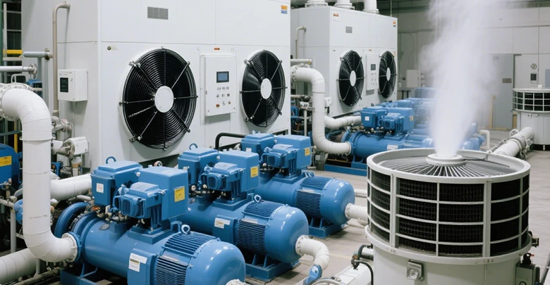
The CDU is not just a heat exchanger; it is the hydraulic and chemistry boundary between the technology cooling system (TCS) and the facility water system (FWS). A liquid-to-liquid CDU with plate heat exchangers typically operates at a 4–5 °C approach temperature, while a liquid-to-air equivalent is closer to 15 °C. A lower approach temperature improves cooling efficiency but usually requires more heat-exchanger surface or higher facility water flow. Specify the approach at the design heat load, not at a nominal condition.
1.2 Facility Water Temperature Interface and ASHRAE Classes
The facility water supply temperature class sets the upper bound for the TCS supply temperature. ASHRAE W-classes (W17, W27, W32, W40, W45, W+) define the maximum facility water supply temperature in °C; for example, W27 means the facility water supplied to the IT equipment is at or below 27 °C. The CDU approach then determines the achievable TCS supply temperature: T_TCS,supply ≈ T_FWS,supply + approach. If the cold plate design requires a lower TCS supply temperature than the facility water plus achievable approach can provide, the facility water temperature or the CDU must change — not just the cold plate.
Confirm the facility water temperature window across summer and winter, the allowable pressure drop on the facility side, and the water quality class (W1–W4). A CDU with a low approach may be wasted if the facility water temperature already meets the TCS requirement; conversely, a high approach can force unnecessary chiller operation.
1.2.1 Facility Water Class to TCS Supply Temperature: A Budget Table
| Facility water class | Max facility supply temperature | CDU approach (liquid-to-liquid) | Approximate achievable TCS supply | Implication for cold plate design |
|---|---|---|---|---|
| W17 | ≈ 17 °C | 4–5 °C | ≈ 21–22 °C | Low TCS supply; cold plate thermal resistance can be relaxed |
| W27 | ≈ 27 °C | 4–5 °C | ≈ 31–32 °C | Moderate; most single-phase cold plates can meet typical component limits |
| W32 | ≈ 32 °C | 4–5 °C | ≈ 36–37 °C | Tighter thermal-resistance budget; TIM and spreading become critical |
| W40 / W45 | ≈ 40–45 °C | 4–5 °C | ≈ 44–50 °C | Cold plate alone may not meet junction limits; chiller or lower-approach CDU may be required |
The table is a planning aid, not a specification. Confirm the facility water class, the CDU approach at the design heat load, and the component temperature limit before fixing the cold plate thermal-resistance target. If the achievable TCS supply plus the cold plate resistance exceeds the component limit, the fix is in the facility water, the CDU, or the system architecture — not in the cold plate channel geometry alone.
1.3 Control Strategy, Flow Distribution, and Pressure Budget
When several cold plates operate in parallel, branch resistance and manifold pressure affect individual flow rates. A total loop flow measurement may conceal a starved branch. Balance the branches through hydraulic design and verify flow distribution under expected operating conditions.
The control strategy should define: whether flow is fixed or variable; how pump speed responds to load or temperature; what happens during a partial flow loss or pump failure; and how the CDU maintains TCS supply temperature above the dew point to prevent condensation. Reserve pressure budget for the complete loop and account for filter loading over time. Evaluate performance at nominal and worst-case conditions, including reduced flow and higher inlet temperature.
1.4 Integration Differences Across Data Centers, EVs, and Power Electronics
Data centers: Priorities include serviceability, leak containment, rack-level distribution, predictable flow, monitoring, and compatibility with the facility cooling architecture.
Electric vehicles: Weight, vibration, shock, packaging, coolant freeze protection, corrosion, pressure cycling, and service life are important. Battery plates must also account for cell spacing and temperature uniformity.
Power electronics: Designers must consider localized semiconductor hotspots, electrical isolation requirements, mounting pressure, transient loads, and the thermal path from the device package into the plate.
2. Cold Plate Applications: Data Centers, EVs, Power Electronics, Medical Equipment, and Aerospace
2.1 Cold Plate for Data Centers and AI Accelerators
Cold plates remove heat directly from CPUs, GPUs, and other high-power devices. A single high-density AI rack can draw well over 100 kW, with the majority going to cold plates and the remainder still rejected to air. Design priorities include hotspot control, temperature uniformity, predictable pressure drop, reliable seals, serviceable connections, and compatibility with rack-level coolant distribution.
Specific constraints: OCP-oriented single-phase direct-to-chip cold plates are often specified with fluid velocities below about 1.5 m/s to limit erosion, wetted-metal galvanic potential difference below about 0.15 V, and flush residue limits in the tens-of-micrometres range. Flow per OAM cold plate is commonly in the 1–2 L/min range, with rack-level flows an order of magnitude higher.
Design emphasis: low thermal resistance at the device footprint, manifold balance across parallel plates, and leak containment at quick disconnects. The cold plate must be designed against the rack CDU’s available TCS supply temperature and pressure budget, not in isolation.
2.2 Cold Plate for EV Batteries and Power Electronics
Battery thermal-management plates aim to keep cells within their specified temperature range and limit cell-to-cell temperature variation across the pack. Plate geometry must fit the module layout while meeting mass, pressure, vibration, corrosion, and packaging constraints.
Specific constraints: coolant freeze protection (often water-glycol), pressure cycling, road vibration and shock, and long service life. For power electronics, localized semiconductor hotspots, electrical isolation, mounting pressure, and transient loads dominate. A cold plate that performs well on a uniform battery heat load may fail on a small inverter hotspot at the same total power.
Design emphasis: uniform cooling and robust joining for battery plates; low spreading resistance and reliable contact for power electronics. Mass and cost are usually tighter constraints than in data-center cold plates.
2.3 Cold Plate for Medical Equipment and Imaging
Medical imaging and diagnostic equipment may use cold plates to manage heat from compact electronics, power supplies, and other heat-generating subsystems. Low noise, stable temperatures, limited space, maintainability, and material compatibility may matter more than maximizing heat flux.
Specific constraints: acoustic noise, cleanability, biocompatibility of wetted materials where applicable, and long unattended operating hours. Service access is often restricted, so leak risk and connector reliability are critical.
Design emphasis: quiet, predictable thermal management with conservative pressure and leak margins; documentation for regulatory review may be as important as thermal performance.
2.4 Cold Plate for Aerospace and Defense
Aerospace and defense systems may require substantial heat removal within strict mass and space limits. Vibration, shock, pressure, and environmental exposure can impose demanding design constraints.
Specific constraints: mass, vibration and shock spectra, altitude and temperature extremes, fluid compatibility, inspectability, and program-specific qualification evidence. A design that is thermally adequate but not inspectable or traceable will not pass qualification.
Design emphasis: validated performance and robust construction, with material and process traceability from prototype through production.
2.5 Design Priorities by Application
| Application | Primary Thermal Concern | Important Constraints | Design Emphasis |
|---|---|---|---|
| AI servers and data centers | High device power and localized hotspots | Serviceability, rack distribution, leakage, pressure budget | Low thermal resistance and predictable flow |
| EV batteries | Cell temperature range and uniformity | Weight, vibration, corrosion, packaging, service life | Uniform cooling and robust joining |
| EV power electronics | Concentrated semiconductor heat | Transient loads, electrical requirements, mounting | Low spreading resistance and reliable contact |
| Medical equipment | Stable component temperatures | Noise, compactness, maintenance, safety requirements | Quiet and predictable thermal management |
| Aerospace and defense | High power density in a constrained envelope | Mass, vibration, shock, environmental qualification | Validated performance and robust construction |
3. Future Trends: AI Optimization, Additive Manufacturing, Digital Twins, and New Coolants
3.1 AI-Assisted and Surrogate-Based Optimization
AI-assisted workflows can screen design variants, approximate simulation results, and prioritize candidates for detailed CFD. Their value depends on representative training data, clearly defined constraints, and verification of promising designs.
AI methods complement rather than replace engineering judgment, physics-based simulation, and physical testing.
3.2 Additive Manufacturing and Lightweight Geometries
Additive manufacturing may enable integrated manifolds, conformal cooling passages, and complex internal surfaces. Adoption depends on repeatable feature quality, internal cleanliness, inspection, material properties, and total production cost.
Develop designs around the intended manufacturing process and post-processing route from the beginning.
3.3 Digital Twins and Operating Monitoring
A digital twin combines a model with operating data to estimate system state and support diagnostics or maintenance. Useful liquid-cooling inputs may include coolant inlet and outlet temperatures, flow rate, pressure, pump status, and component temperature.
Sensor quality, model calibration, and clear fault thresholds are necessary for reliable predictions.
3.4 Dielectric Fluids, Nanofluids, and Two-Phase Cooling
Dielectric fluids may be relevant where electrical isolation is required, but their thermal properties, viscosity, material compatibility, and cost must be considered.
Nanofluids are being investigated for possible heat-transfer improvements, yet stability, pressure drop, fouling, erosion, and long-term reliability can limit practical use.
Two-phase cooling can provide high heat-transfer capacity through phase change, but introduces control, pressure, flow-stability, and system-complexity challenges. Evaluate these technologies against a defined application and validate them under representative operating conditions.
4. Frequently Asked Questions About Cold Plates and Suppliers
4.1 What Is the Difference Between a Cold Plate and a Heat Sink?
A conventional heat sink transfers heat to air across exposed fins, while a liquid cold plate transfers heat to coolant flowing through internal passages. A cold plate is often useful when heat flux is high or space is limited, but it requires a liquid loop with a pump, plumbing, and heat-rejection equipment. The right choice depends on heat load, ambient conditions, system complexity, and lifecycle requirements.
4.2 How Many Watts Can a Cold Plate Dissipate?
There is no universal wattage rating. A cold plate’s capability is set by the heat-source footprint and heat-flux distribution, the allowable junction or case temperature, the coolant inlet temperature, the achievable flow rate, the channel geometry, the material, and the pressure-drop limit. A plate that handles several hundred watts on a large, uniform heat source may fail on a small hotspot at the same total power. Specify the heat-flux map and the temperature limit first, then calculate or measure the maximum temperature and pressure drop under those conditions. Do not select a cold plate from a single wattage number.
4.3 Which Coolant Should Be Used in a Cold Plate?
The coolant must match the operating temperature range, heat-capacity requirements, viscosity limits, corrosion-control strategy, and compatibility of all wetted materials and seals. Water transfers heat effectively, while water-glycol mixtures can provide freeze protection with different thermal and hydraulic properties. Follow the system specification and validate coolant compatibility before operation.
4.4 Should I Choose a Copper or Aluminum Cold Plate?
Copper generally offers higher thermal conductivity and can be preferable when heat spreading is critical. Aluminum is lighter and often attractive for large or cost-sensitive designs. Compare geometry, coolant, corrosion risk, manufacturing method, pressure rating, and lifecycle cost rather than choosing based on conductivity alone.
4.5 How Do I Choose a Cold Plate Supplier?
Start with the supplier category (see Section 5), then apply the scorecard in Section 6. Confirm that the supplier can produce the required geometry and material using the intended process, control the critical tolerances, and clean and inspect internal passages. Ask how thermal performance and pressure drop are measured, what test data is provided with the part, how process changes are controlled, and how nonconforming parts are handled. Also confirm whether the critical bonding step (vacuum brazing or FSW) is in-house. Compare qualified-part performance and lifecycle risk, not just unit price.
4.6 Are 3D-Printed Cold Plates Reliable?
They can be reliable when material selection, build parameters, post-processing, cleaning, inspection, and qualification are appropriate for the application. Risks include internal roughness, dimensional variation, trapped powder, inaccessible passages, and inconsistent wall thickness. Verify leakage, pressure performance, thermal performance, and durability using parts made with the intended production process.
4.7 How Do You Evaluate Cold Plate Service Life and Corrosion Risk?
Review wetted metals, coolant chemistry, temperature, oxygen exposure, electrical connections between dissimilar metals, and seal materials. Establish corrosion, pressure, leak, vibration, and thermal-cycle tests based on the intended environment and service life. No single short test proves every aspect of long-term durability.
4.8 Does a Cold Plate Need OCP Qualification?
Only when the target platform, procurement specification, or applicable OCP-related program requires it. OCP documents are specific to their scope and revision, so confirm the applicable specification, test methods, and acceptance criteria with the system owner. Do not assume every cold plate requires the same qualification or that a generic test package constitutes universal OCP certification.
5. The Supplier Landscape: Four Categories Before You Score Anyone
Before applying a scorecard, classify the supplier. The categories below have different business models, qualification depth, and commercial terms; comparing a two-phase specialist against a general thermal-component house on the same scorecard produces misleading results.
| Category | What they do | Representative players (examples, not endorsements) | Best fit | What to probe first |
|---|---|---|---|---|
| Liquid-cooling specialists | Focus on single-phase direct-to-chip cold plates, manifolds, and CDUs | CoolIT, Chilldyne, JetCool, Asetek, Iceotope | Data-center GPU/CPU cold plates with platform-specific qualification | Platform-level test data (server model, heat load, flow), not just bare-plate performance |
| Two-phase specialists | Boiling or two-phase cold plates for high heat flux | Accelsius, ZutaCore, ThermAvant, Calyos | Heat fluxes where single-phase is approaching its limit; projects with system-level two-phase experience | Flow-stability data, pressure-control strategy, and field reliability history — not just peak heat-flux claims |
| Thermal-component houses | Broad portfolio: cold plates, heat sinks, heat exchangers, sometimes full loops | Boyd, Wakefield Thermal, Wieland, AVC, Auras | Programs that need one supplier across multiple thermal components or high-volume manufacturing | Process depth for the specific cold-plate route (brazing, FSW, machining), not the breadth of the catalog |
| Server OEM / integrator | Cold plate designed as part of a server or rack platform | Supermicro, Dell, HPE, Lenovo (platform-level offerings) | Programs that want a validated platform rather than a component to integrate | Whether the plate is available as a component or only inside a validated server; service and warranty boundaries |
Most procurement searches start in the specialist categories and end in the component or OEM category when volume and integration risk increase. The scorecard in Section 6 should be applied within a category, not across categories.
6. Supplier Evaluation Scorecard & Bench Testing
6.1 Five Adversarial Questions Before the Scorecard
Before applying a scorecard, use these five questions to screen out vendors who cannot support your exact integration boundary. They are designed to surface hidden assumptions:
- Is this plate tested and warrantied on our exact server and processor? Bare-plate data is not enough; the supplier must have platform-level validation or explicitly state the extrapolation risk.
- At what heat load, flow rate, and coolant was the quoted performance measured? If the supplier cannot provide the test conditions, the thermal resistance number is marketing, not engineering.
- Which couplings and wetted materials are used? A copper plate with aluminum fittings is a galvanic corrosion site waiting to happen.
- What cools everything the plate does not touch? Memory modules, VRMs, and power supplies still need to be cooled; the cold plate is one part of the thermal architecture.
- How does the system protect the processor after a low-flow event, leak, or blocked channel? Leak detection, flow monitoring, and thermal throttling logic should be defined by the system integrator, not left to chance.
6.2 Supplier Evaluation Scorecard
| Criterion | What to ask for | Pass/fail or scoring guidance |
|---|---|---|
| Process capability | Process route, tolerance data, first-pass yield, leak-test data, in-house vs outsourced bonding | Must provide data for the specific process, not a generic capability statement; critical bonding must be in-house for high-volume programs |
| Thermal test capability | Test setup, TIM control, flow and pressure instrumentation, uncertainty | Must report R = (Ts − Ti)/P and pressure-drop curve; a single wattage number is not acceptable |
| Cleanliness and inspection | Cleaning procedure, residue limits, internal inspection method | Must define acceptance criteria for internal cleanliness and hidden features |
| Change control | Process change notification, revalidation triggers | Must have written change-control and revalidation procedure |
| Qualification support | Leak, proof, thermal cycling, vibration, corrosion test reports | Must provide test reports with conditions and acceptance criteria, not just “passed” |
6.3 In-House vs Outsourced Bonding: A Pass/Fail Screen
Before scoring a supplier on thermal test capability or cleanliness, verify whether the critical bonding step — vacuum brazing or FSW — is performed in-house. WinShare’s supplier qualification framework makes this a binary screen, not a preference:
- Use a vendor with in-house FSW when: you require mission-critical leak prevention, high-pressure operation, and single-level internal flow routing.
- Avoid a vendor who outsources brazing or FSW when: production volumes are high. Outsourced bonding adds weeks to lead times and destroys lot-level quality traceability.
The lead-time impact is concrete: outsourced manufacturing typically adds 1–2 weeks for subcontractor scheduling, and suppliers that cannot show their own CNC machining centers, vacuum brazing furnaces, or FSW equipment are likely outsourcing those steps. Ask for factory photos or a virtual factory tour of the specific process, not just a capability statement. A supplier that outsources the critical joint can still be a valid choice for low-volume prototypes, but it should not be scored the same as a vertically integrated supplier on traceability or lead-time risk.
6.4 Bench Testing Supplier Claims
When you receive prototype samples, do not rely on the supplier’s test report alone. Run your own bench test under the intended operating conditions to catch bad thermal claims early:
- Pressure-Drop Loop: Measure Δp at 25%, 50%, 75%, 100%, and 125% of the design flow rate. Compare the measured curve against the supplier’s data sheet. A deviation of more than 15% indicates a dimensional or surface-roughness discrepancy.
- Thermal Resistance Test: Mount the plate with your specified TIM and mounting pressure. Apply the design heat load and measure the case-to-inlet resistance. If it misses the target by more than 20%, check the TIM bond line first, then the flow distribution.
- Leak and Proof: Pressurize to 1.5× working pressure and hold for 30 minutes. Monitor for pressure decay, especially at the port threads and cover joint.
7. Make-or-Buy: When to Build an In-House Cold Plate Capability
In-house capability is usually defensible when the cold plate is tightly coupled to a proprietary system architecture, when the annual volume is high enough to justify the process and test equipment, and when the design changes frequently enough that external DFM cycles become the bottleneck. External supply is usually more defensible when the geometry is standard, when the volume is low or uncertain, and when the required qualification tests and process controls already exist at a qualified supplier. A hybrid model — in-house design and prototype, external production — is common in data-center and EV programs.
8. Tariffs, Origin, and Landed Cost: A Dimension the Scorecard Misses
Unit price is not landed cost. For US-bound programs, China-origin cold plates may be subject to Section 301 tariffs in addition to standard duties; rates and exclusions change over time, so the HTS classification and current rate must be confirmed with a customs broker. The US importer of record pays the tariff unless the supplier quotes DDP (delivered duty paid), which shifts the landed-cost risk to the supplier but usually at a higher unit price.
What the landed-cost gap looks like in practice: ToneCooling’s comparison of equivalent cold plate specifications reports that top-tier Chinese manufacturers offer 40–55% lower total landed cost than US manufacturers. The breakdown is: CNC machining cost 40–60% lower, vacuum brazing cost 50–70% lower, raw material within <5%, and import duty 2.5–7.5% added on the China side. These figures are for “equivalent specifications” and “top-tier” suppliers; the quality gap has narrowed to the point where the top 10–15% of Chinese manufacturers operate with equivalent equipment and certifications (ISO 9001, ±0.01 mm CNC tolerance, helium leak to 10⁻⁶ mbar·L/s, Zeiss/Hexagon CMM).
But the tariff picture can dominate the landed-cost calculation. Section 301 tariffs may apply on top of the standard duty, and rates and exclusions change over time. Some trade-policy scenarios have discussed China-origin cooling hardware at rates far above the standard duty range, which would erase the manufacturing-cost advantage entirely. The scorecard should therefore separate manufacturing cost advantage (the 40–55% figure above) from tariff exposure (which depends on HTS classification, current Section 301 scope, and whether the supplier quotes DDP). A supplier that quotes DDP shifts the landed-cost risk to itself, usually at a higher unit price; a supplier that quotes FOB leaves the importer of record exposed to tariff changes.
9. Conclusion and Next Steps: How to Start a Cold Plate Design
9.1 Cold Plate Design Checklist
- Define total heat load, heat-flux distribution, hotspot locations, and allowable component temperatures.
- Specify coolant type, inlet temperature range, flow range, and material compatibility.
- Set a cold plate pressure-drop limit within the complete system pressure budget.
- Select candidate materials and construction methods based on thermal, mechanical, weight, cost, and manufacturing requirements.
- Define channel geometry, fin dimensions, manifold layout, port locations, and sealing interfaces.
- Evaluate thermal resistance, coolant temperature rise, pressure drop, and pump power.
- Use CFD where three-dimensional flow or heat-transfer behavior requires it, and validate the model against test data.
- Plan leak, pressure, thermal, corrosion, vibration, and thermal-cycle tests as applicable.
- Establish DFM reviews, cleaning requirements, dimensional inspection, traceability, and change control.
9.2 When Is CFD Necessary?
Use simplified calculations for initial sizing, straightforward channels, and preliminary pressure-drop estimates. CFD becomes more valuable when the design has complex manifolds, parallel flow paths, localized hotspots, nonuniform heat input, intricate fins, or tight temperature and pressure limits.
Simulation is also useful when testing reveals behavior that simplified models cannot explain. It should support, not replace, physical validation.
9.3 Prepare the Inputs for a Design Review — and Choose the Right Next Step
Prepare the heat-source drawing or heat-flux map, component temperature limits, coolant specification, inlet temperature, target flow range, allowable pressure drop, mechanical envelope, port requirements, material preferences, and operating environment. If available, include the system pressure curve, mounting interface, and required qualification tests.
With those inputs ready, the next step depends on what you are trying to decide:
9.3.1 If You Need a First-Pass Number Before Contacting a Supplier
Use a cold plate system calculator to check whether a proposed geometry can keep the mounting surface below its temperature limit, and to see the flow, pressure drop, and pump power the geometry demands. A calculator is for concept screening: it assumes uniform heat input, equal channel distribution, and clean internal surfaces. It does not replace CFD or test data for hotspots, manifold maldistribution, or TIM/contact resistance.
Next step: run the calculator, then send the heat-flux map, coolant conditions, pressure-drop limit, and mechanical drawing for a free drawing feasibility review and a first-pass thermal evaluation.
9.3.2 If You Are Comparing Design Concepts or Need Hotspot Resolution
Use conjugate heat transfer CFD when the design has complex manifolds, parallel flow paths, localized hotspots, nonuniform heat input, or tight temperature and pressure limits. Compare maximum component temperature, temperature uniformity, pressure drop, and pump power under identical boundary conditions. Require mesh-independence and a validation case against measured data.
Next step: upload the geometry and operating conditions for a CFD-based concept comparison, or ask for a simulation scope that includes manifold maldistribution and hotspot mapping.
9.3.3 If You Need a Manufacturable Part and a Supplier Quote
Prepare the heat-source drawing or heat-flux map, component temperature limits, coolant specification, inlet temperature, target flow range, allowable pressure drop, mechanical envelope, port requirements, material preferences, and operating environment. If available, include the system pressure curve, mounting interface, and required qualification tests.
Send these inputs to a qualified cold-plate manufacturer for a DFM review and a first-pass thermal-hydraulic estimate. Ask for the calculation assumptions, not just a conclusion. For a faster first response, include the manufacturing process preference (CNC / gun-drilled / brazed / FSW / additive) and the expected production volume.
Manufacturer capability check: confirm that the supplier can produce the required geometry and material, control critical tolerances, seal and clean internal passages, inspect hidden features, and provide traceable test results. Ask how thermal performance and pressure drop are measured, how process changes are controlled, and how nonconforming parts are handled. Confirm whether the critical bonding step is in-house.
Ready to Source Your Cold Plate?
We evaluate, DFM-review, and manufacture cold plates for data centers, EV power electronics, and medical equipment. Don’t settle for a supplier who only quotes a single wattage number.
Send us your inputs for a free DFM review and first-pass thermal evaluation:
- Heat-flux map or total power load
- Coolant type, inlet temperature, and target flow rate
- Allowable pressure drop limit
- Mechanical envelope or 3D CAD drawing
Contact the Thermal Team & Request a Quote
Not ready to talk? Run a first-pass cold plate calculation or download our design checklist to prepare your RFQ.