Extruded heat sink design depends mainly on fin height, fin pitch, base thickness, airflow condition, material, heat load and extrusion feasibility. A good design should provide enough heat transfer surface area while keeping airflow resistance, weight, tooling complexity and manufacturing cost under control.
For aluminum extrusion heat sinks, the geometry is formed through a die, which means the cross-sectional profile must be thermally effective and manufacturable at the same time. Engineers cannot simply make fins taller, thinner or denser without considering air movement, extrusion limits, base strength and assembly requirements.
Fin height increases surface area, but overly tall fins may be difficult to extrude or may not perform well if airflow cannot reach the full fin area. Fin pitch affects how air passes through the heat sink; narrow gaps can improve surface area under forced air but may restrict natural convection. Base thickness affects heat spreading from the component into the fins, but excessive thickness adds weight and material cost.
This guide explains how fin height, fin pitch and base thickness affect extruded aluminum heat sink performance, helping engineers and buyers make practical design decisions before ordering a custom extruded heat sink.
The Three Geometry Decisions That Shape an Extruded Heat Sink
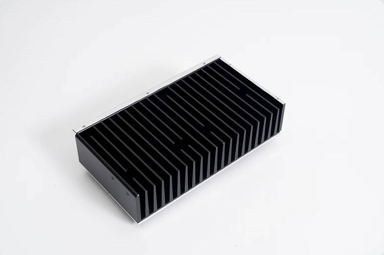
An extruded heat sink is formed by pushing heated aluminum through a die to create a continuous profile. Because the same cross-section repeats along the length, the profile geometry becomes the foundation of thermal performance.
Three design parameters usually control the profile:
| Design Parameter | Main Function | Main Risk If Poorly Designed |
| Fin height | Increases surface area for heat dissipation | Tall fins may be inefficient if airflow is weak |
| Fin pitch | Controls air movement between fins | Narrow pitch may increase airflow resistance |
| Base thickness | Spreads heat from component to fins | Too thin causes hot spots; too thick adds weight and cost |
The best extruded heat sink profile is not the one with the tallest fins or the thickest base. It is the one that matches the heat source, airflow and manufacturing process.
This is why custom heat sink design should begin with the application conditions, not with a fixed profile copied from another product.
Fin Height: More Surface Area, But Not Always More Cooling
Fin height is one of the first parameters engineers adjust when trying to improve heat sink performance. Taller fins increase surface area, which can improve convective heat transfer if air can move effectively along the fins.
However, fin height also affects extrusion feasibility, mechanical stability, airflow resistance and weight.
How Fin Height Affects Thermal Performance
When fins are taller, more metal surface is exposed to air. This can help dissipate more heat, especially under forced airflow. But the upper part of a very tall fin may not always contribute efficiently if heat does not conduct well from the base to the fin tip or if airflow is limited.
In practical terms:
- Short fins are easier to extrude and mechanically stable, but surface area may be limited.
- Medium-height fins often provide a good balance for many electronics cooling designs.
- Tall fins can improve performance in airflow-supported systems, but they require careful fin thickness, spacing and extrusion review.
Fin height should be selected according to available airflow and heat load, not simply increased to make the heat sink look more powerful.
Fin Height Design Considerations
| Fin Height Condition | Suitable Situation | Engineering Concern |
| Low fin height | Low-profile electronics, limited space | Surface area may be insufficient for higher heat load |
| Medium fin height | General electronics, power supplies, telecom modules | Often easier to balance performance and manufacturability |
| Tall fin height | High power devices with available airflow | Extrusion feasibility, fin strength and air distribution must be checked |
| Very tall and thin fins | Compact forced-air cooling | May increase tooling difficulty and fin deformation risk |
For high power electronics, fin height should be reviewed together with base thickness. A tall fin structure cannot solve the problem if heat does not spread from the component into the fin field efficiently.
Fin Pitch: The Airflow Parameter Buyers Often Underestimate
Fin pitch is the distance between adjacent fins. It determines how easily air can move through the heat sink. This makes it one of the most important parameters in extruded heat sink design.
A narrow fin pitch increases the number of fins and surface area. But if the gap is too narrow, air cannot pass through effectively, especially in natural convection. A wider pitch reduces airflow resistance but may reduce total surface area.
Natural Convection vs Forced Air
Fin pitch should be selected based on airflow mode.
| Cooling Condition | Fin Pitch Direction | Reason |
| Natural convection | Wider spacing is often preferred | Air needs room to rise between fins |
| Low-speed fan cooling | Moderate spacing is usually practical | Balances surface area and pressure drop |
| Strong forced airflow | Narrower pitch may be considered | Fan pressure can push air through denser fins |
| Dusty environment | Wider spacing may help | Reduces blockage risk and cleaning difficulty |
| Ducted airflow | Pitch should match fan static pressure | Too narrow may increase pressure drop |
Fin pitch must match the real airflow condition. A dense fin array may perform poorly if the system cannot push enough air through the gaps.
This is especially important for outdoor telecom equipment, sealed power electronics cabinets, LED systems and industrial control devices where airflow may be limited or inconsistent.
Base Thickness: Heat Spreading Before Heat Dissipation
The base of a heat sink transfers heat from the component into the fins. If the base is too thin, heat may remain concentrated near the source and only a small part of the fin field will be used effectively. If the base is too thick, the heat sink becomes heavier and more expensive without necessarily improving performance.
Base thickness must balance heat spreading, mechanical strength, machining needs and weight.
What Base Thickness Controls
| Base Thickness Function | Why It Matters |
| Heat spreading | Helps distribute heat from the component to multiple fins |
| Mounting strength | Supports screws, clamps, inserts or module pressure |
| Surface flatness | Affects thermal interface contact |
| Machining allowance | Supports drilling, tapping and milling |
| Structural stiffness | Reduces deformation during assembly |
| Material cost | Thicker base increases material usage and weight |
For components with a small contact area, a thicker base may help spread heat laterally. For components with a large contact area, excessive base thickness may not provide much benefit.
Thin Base vs Thick Base
| Base Design | Advantage | Limitation |
| Thin base | Lower weight and material cost | May create hot spots under concentrated heat sources |
| Medium base | Balanced heat spreading and cost | Requires application-specific review |
| Thick base | Better mechanical strength and lateral spreading | Higher weight, cost and thermal path length |
| Locally thickened base | Supports hot spots or mounting areas | May require more complex extrusion or machining |
Base thickness should be designed around the heat source size and mounting method, not selected as a fixed standard for every project.
How Fin Height, Pitch and Base Thickness Work Together
These three parameters cannot be optimized separately. Changing one often affects the others.
For example:
- Taller fins may need wider spacing to avoid airflow restriction.
- Narrower fin pitch may require stronger forced airflow.
- A thinner base may need more careful heat source placement.
- A thicker base may allow better spreading but increases weight.
- Dense fins may improve surface area but increase pressure drop for fans.
- Wide fin gaps may support natural convection but reduce surface area.
Engineering Parameter Matrix
| Design Goal | Fin Height | Fin Pitch | Base Thickness |
| Low-profile electronics | Lower | Moderate | Thin to medium |
| Natural convection | Medium | Wider | Medium depending on heat source |
| Forced-air cooling | Medium to tall | Moderate to narrow | Medium |
| High power module | Taller if airflow supports it | Designed around fan pressure | Medium to thick |
| Cost-sensitive production | Avoid excessive height | Keep extrusion simple | Avoid unnecessary thickness |
| Compact high heat load | Tall or dense fins may be needed | Requires airflow review | May need thicker base |
| Outdoor equipment | Durable fin design | Avoid overly narrow gaps | Enough strength for mounting |
The most reliable approach is to define the thermal requirement first, then build the profile around airflow and manufacturability.
Extrusion Feasibility: Design Must Pass the Die
An extruded heat sink must be manufacturable through an extrusion die. This creates practical limits for fin aspect ratio, fin thickness, base shape and profile complexity.
Engineers may want extremely thin and tall fins, but the material must flow through the die consistently. A profile that is too aggressive may increase tooling difficulty, dimensional variation, surface issues or production cost.
Extrusion Feasibility Checklist
| Design Question | Why It Matters |
| Are the fins too tall relative to the gap? | High aspect ratios may be difficult to extrude consistently |
| Is the fin thickness realistic? | Very thin fins may deform or be hard to control |
| Is the base too thick compared with fin sections? | Uneven material flow may affect extrusion quality |
| Are there sharp corners or difficult cavities? | Tooling and material flow become more complex |
| Is the profile symmetrical or highly unbalanced? | Unbalanced profiles may twist or distort |
| Will post-machining be required? | Mounting holes, slots and flat surfaces may need CNC work |
| Is surface treatment planned? | Anodizing or coating may affect final dimensions |
| Is the length variable? | Extrusion is strong when the same profile can be cut to different lengths |
A custom extrusion profile should be reviewed by both thermal and manufacturing teams before tooling. If the profile is thermally attractive but difficult to extrude, the design may need adjustment.
Jindu Tech provides custom extruded heat sinks for projects where profile design, CNC machining, surface treatment and thermal requirements need to be evaluated together.
Matching Extruded Heat Sink Design to Applications
Different industries require different fin structures. A design that works for a fan-cooled server module may not work for outdoor passive telecom equipment.
Application-Based Design Direction
| Application | Common Thermal Challenge | Design Direction |
| Telecom equipment | Outdoor operation and natural convection | Wider fin pitch, durable profile, corrosion-resistant finish |
| Power electronics | High heat load and concentrated modules | Medium to tall fins, sufficient base thickness, forced-air review |
| LED lighting | Cost, appearance and passive cooling | Moderate fins, good surface treatment, weight control |
| Industrial controls | Continuous operation in cabinets | Balanced fin pitch, stable mounting, dust consideration |
| Server hardware | Limited space and directed airflow | Dense fins if fan pressure supports it |
| Renewable energy inverter | Outdoor reliability and power density | Strong base, controlled airflow path, protective finish |
| Medical equipment | Quiet operation and clean assembly | Passive or low-noise airflow design, clean surface finish |
| Automotive electronics | Vibration, weight and compact layout | Robust fins, controlled mass, stable mounting |
This application matching step helps prevent overdesign. For example, a high-density fin profile may be useful in a fan-cooled server, but less effective in natural convection outdoor equipment.
Airflow Matching Table for Fin Pitch Decisions
Fin pitch should be chosen after the airflow condition is known.
| Airflow Situation | Fin Pitch Recommendation | Design Note |
| No fan, vertical orientation | Wider pitch | Supports buoyancy-driven air movement |
| No fan, horizontal orientation | Conservative fin height and pitch | Natural convection may be weaker |
| Low-speed fan | Moderate pitch | Avoid excessive pressure drop |
| High-speed fan | Narrower pitch may be possible | Confirm fan static pressure |
| Dust or outdoor exposure | Avoid overly narrow pitch | Reduces clogging and maintenance risk |
| Ducted airflow | Pitch should match duct and fan design | Test under real airflow path |
| Unknown airflow | Start with moderate pitch | Validate with prototype testing |
Fin pitch is an airflow decision as much as a geometry decision.
For B2B custom projects, buyers should provide fan specifications, airflow direction and installation orientation whenever possible. Without airflow data, suppliers can only make conservative assumptions.
Base Design for Mounting and Thermal Contact
Base thickness is not the only base-related design parameter. Mounting holes, contact surface, flatness, inserts and thermal interface material also affect performance.
Base Design Factors
| Base Factor | Impact |
| Contact area | Determines heat transfer into the heat sink |
| Flatness | Affects thermal interface resistance |
| Mounting pressure | Influences contact stability |
| Hole position | Affects assembly and stress distribution |
| Thread depth | Requires enough base material |
| Surface finish | Affects contact and coating |
| TIM selection | Influences total thermal resistance |
| Electrical insulation | May be needed for some power modules |
A well-designed base should provide a stable thermal path and reliable mechanical connection. If the base is too thin for the mounting method, deformation or poor contact may occur. If the base is too thick, cost and weight may increase without proportional thermal improvement.
When Extrusion Is Not Enough
Extruded heat sinks are widely used because they are cost-effective and scalable. However, extrusion is not suitable for every cooling requirement.
Consider another heat sink process when:
- The heat source is extremely compact and intense
- The required fin density exceeds extrusion feasibility
- The geometry is not a constant cross-section
- The system needs heat transfer to a remote fin area
- The heat sink must include complex 3D features
- Weight or space is extremely restricted
- Thermal testing shows the extrusion profile cannot meet the target
Possible alternatives may include skived fin heat sinks, bonded fin heat sinks, heat pipe heat sinks, die cast heat sinks, cold forged heat sinks or CNC machined heat sinks, depending on the application.
This does not reduce the value of extrusion. It simply means extrusion should be selected when its strengths match the project: linear profiles, repeatable production, cost control and practical aluminum heat sink geometry.
Cost Drivers in Extruded Heat Sink Design
Extruded heat sink cost is affected by more than raw aluminum weight.
Major Cost Drivers
| Cost Driver | How It Affects Cost |
| Custom extrusion die | Adds upfront cost for new profiles |
| Profile complexity | More difficult fin structures may increase tooling cost |
| Fin height and aspect ratio | Aggressive designs may raise extrusion difficulty |
| Base thickness | More material increases weight and cost |
| Cut length | Affects material use and handling |
| CNC post-processing | Drilling, tapping and milling add machining time |
| Surface treatment | Anodizing, coating or finishing adds process cost |
| Tolerance requirements | Tighter tolerances require more inspection and machining |
| Production volume | Higher volume can spread tooling cost |
| Packaging requirements | Protects fins during shipment |
A cost-effective extruded heat sink is designed for both thermal performance and manufacturability.
If the design is too complex for extrusion, the project may face tooling revisions, higher unit cost or production delays.
RFQ Specification Checklist for Custom Extruded Heat Sinks
To receive a useful design review and quotation, buyers should prepare the following information.
| Information to Provide | Why It Helps |
| Heat load | Defines cooling requirement |
| Heat source size and location | Helps determine base thickness and fin field |
| Maximum allowable temperature | Sets thermal target |
| Available space | Defines length, width and height limits |
| Airflow condition | Determines fin pitch and fin height direction |
| Fan specification | Helps evaluate dense fin feasibility |
| Installation orientation | Important for natural convection |
| Material preference | Supports aluminum alloy selection |
| Surface treatment requirement | Supports corrosion and appearance planning |
| Mounting method | Affects base thickness and machining |
| Production volume | Determines tooling and cost strategy |
| Drawing or 3D model | Improves extrusion feasibility review |
| Tolerance requirements | Defines machining and inspection scope |
| Application environment | Helps evaluate dust, vibration, humidity and outdoor exposure |
Jindu Tech provides custom extruded heat sink solutions for projects where fin geometry, base design, CNC machining and application requirements need to be reviewed together.
For customers comparing broader thermal management technologies, Jindu Tech’s thermal solutions overview can help review related heat sink and cold plate product directions.
Practical Design Review Before Tooling
Before creating an extrusion die, the design should be reviewed from three directions: thermal performance, manufacturability and assembly.
Pre-Tooling Review Checklist
| Review Area | Questions to Confirm |
| Thermal | Does the profile meet the heat load and temperature target? |
| Airflow | Is the fin pitch matched to natural convection or fan cooling? |
| Extrusion | Can the fin height, gap and base shape be extruded consistently? |
| Machining | Are mounting holes, slots and flatness requirements feasible? |
| Surface treatment | Will anodizing or coating affect final tolerance? |
| Assembly | Can the heat sink be mounted without bending or poor contact? |
| Cost | Is the profile overdesigned for the actual thermal requirement? |
| Testing | What validation is needed before mass production? |
This step is especially important when the heat sink will be used in power electronics, telecom, outdoor equipment or industrial systems where redesign can delay product launch.
FAQ
What is extruded heat sink design?
Extruded heat sink design is the process of defining an aluminum profile with suitable fin height, fin pitch, base thickness, material and machining features for thermal performance and manufacturability. The profile is produced through an extrusion die and then cut or machined as needed.
How does fin height affect heat sink performance?
Fin height increases surface area, which can improve heat dissipation when airflow can reach the fins effectively. However, overly tall fins may be difficult to extrude, mechanically weaker or inefficient if airflow is limited. Fin height should match heat load and airflow conditions.
What is the best fin pitch for an aluminum extrusion heat sink?
There is no single best fin pitch. Wider pitch is often better for natural convection, while narrower pitch may work with forced airflow. The right fin pitch depends on airflow speed, fan pressure, dust exposure, heat load and available heat sink size.
Why is base thickness important in heat sink design?
Base thickness helps spread heat from the component into the fin field and provides mechanical strength for mounting. A base that is too thin may create hot spots, while a base that is too thick can increase weight and cost without proportional thermal benefit.
When should I use an extruded aluminum heat sink?
Use an extruded aluminum heat sink when the design can use a constant cross-sectional profile, production repeatability matters, cost control is important and the thermal requirement can be met with fin geometry and airflow optimization.
Can extruded heat sinks be used for high power electronics?
Yes, extruded heat sinks can be used for high power electronics when the base, fin height, fin pitch and airflow are properly designed. For extremely high heat density, engineers may also compare skived, bonded fin or heat pipe assisted designs.
What information is needed for a custom extruded heat sink quote?
Buyers should provide heat load, heat source size, available space, airflow condition, target temperature, material preference, surface treatment, mounting method, production volume, drawings or 3D files and tolerance requirements.
Is a taller fin always better for heat sink cooling?
No. Taller fins increase surface area, but they may not improve cooling if airflow is weak or if the fin becomes inefficient near the tip. The fin height must be balanced with fin pitch, base thickness, airflow and manufacturability.
Conclusion
Extruded heat sink design is a balance between thermal performance, airflow, manufacturability and cost. Fin height determines surface area, but must match airflow and extrusion feasibility. Fin pitch controls air movement, but should be selected based on natural convection or forced cooling. Base thickness supports heat spreading and mounting, but excessive thickness increases weight and material cost.
A practical extruded aluminum heat sink is not designed by maximizing every dimension. It is designed by matching fin height, fin pitch and base thickness to the real heat load, airflow path and production process.
For electronics, power modules, telecom equipment, LED lighting, industrial control systems and renewable energy devices, extrusion can provide a scalable and cost-effective cooling solution when the profile is engineered correctly.
If your project requires a custom aluminum extrusion heat sink, Jindu Tech can review your heat load, airflow condition, space limit and drawings to evaluate a suitable extruded heat sink design.