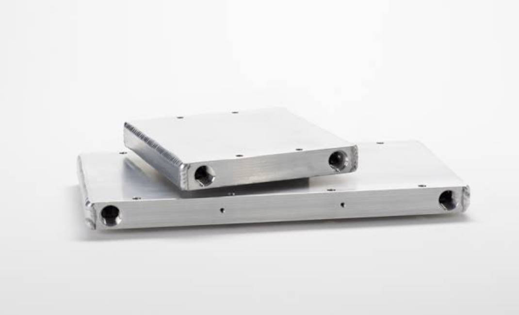
The flow channel layout decides how coolant moves inside a liquid cold plate, and that single choice drives pressure drop, temperature uniformity, and pumping power. In a parallel flow channel the coolant splits into several paths that share the same cold inlet, while in a series (serpentine) flow channel the entire flow travels one continuous path from inlet to outlet. Neither topology is universally better; the right choice depends on heat flux distribution, available pumping head, and how uniform the surface temperature must stay.
What Is a Flow Channel in a Liquid Cold Plate?
A flow channel is the internal passage machined, brazed, or drilled into a cold plate through which the liquid coolant circulates to carry heat away from the mounted component. At JinduTech liquid cold plates, these internal flow paths are engineered rather than left generic: our team uses CFD to balance heat transfer against hydraulic resistance before a plate is built. The geometry of the channel—its width, depth, length, and how branches connect—determines whether coolant arrives at every hot spot with enough capacity to absorb heat.
Parallel Flow Channel Design
How parallel flow channels work
In a parallel layout the inlet manifold distributes the total flow into two or more separate channels that run side by side and rejoin at the outlet manifold. Because each branch starts from the same plenum, every channel receives coolant at roughly the same inlet temperature and pressure.
Advantages of parallel flow channels
Parallel designs are common for large, evenly heated surfaces because they keep the contact temperature steady across the plate. They also keep the overall pressure drop low: the pump only has to push the flow rate of a single branch, not the entire volume through one long path.
Limitations and failure modes
The main weakness is flow maldistribution. If one branch is shorter, wider, or has less resistance than the others, it steals more flow and the starving branches run warmer. Manifold design, channel tolerances, and even air pockets can break the balance. Flow maldistribution is the dominant risk of parallel flow channel design and is usually traced to uneven manifold resistance or inconsistent channel geometry.
Series (Serpentine) Flow Channel Design
How series flow channels work
A series layout sends the full flow through one long, often snaking channel. The coolant enters cold, absorbs heat along the way, and exits warmer. There is no branching, so every part of the path sees the complete flow rate.
Advantages of series flow channels
Because there is no splitting, a series path avoids maldistribution entirely—the whole flow is committed to the entire surface. This makes it predictable for concentrated or irregular heat loads. A series flow channel produces a measurable temperature gradient from inlet to outlet, which is useful when you want the coolant to sweep the hottest zone last.
Limitations
The trade-off is pressure drop. Forcing the entire flow through a long path raises the required pumping pressure, and the outlet end of the plate runs hotter than the inlet end, creating a hotspot if the heat load is also highest there.
Parallel vs Series: Side-by-Side Comparison
| Factor | Parallel flow channel | Series (serpentine) flow channel |
|---|---|---|
| Pressure drop | Low (flow split across branches) | High (full flow through one long path) |
| Temperature uniformity | Good when balanced; varies if maldistributed | Gradient inlet to outlet; predictable |
| Flow distribution risk | High (maldistribution possible) | None (no branching) |
| Pumping power | Lower | Higher |
| Hotspot control | Depends on balance | Outlet-end hotspot if load peaks there |
| Best for | Large, uniform heat loads; low pressure-drop budget | Concentrated flux; irregular loads; simple sealing |
Key Factors That Influence the Choice
- Heat flux distribution: uniform loads favor parallel; peaked loads often need series or hybrid.
- Available pumping head: tight pressure-drop budgets push toward parallel.
- Surface temperature limit: if the spec demands tight uniformity, a balanced parallel or a hybrid serpentine-in-parallel wins.
- Coolant type: two-phase or viscous coolants amplify maldistribution in parallel layouts.
- Manufacturability: deep-drilled or extruded plates suit parallel; brazed fins suit complex series paths.
Pressure Drop and Pumping Power: What to Expect
Pressure drop scales with flow velocity squared and total path length. In a parallel plate the per-branch velocity is the total flow divided by the number of branches, so the system pressure drop is closer to that of a single branch. In a series plate the velocity is the full flow, so the pressure drop is higher for the same total coolant rate. In many applications the difference is enough to change pump selection from a low-head to a higher-head unit. As a cautious rule, series paths commonly need noticeably more pumping head than an equivalent parallel layout; exact values depend on channel hydraulic diameter, length, coolant viscosity, and fitting losses, so they should be computed per design rather than assumed.
Coolant Velocity and the Heat Transfer Trade-off
Beyond topology, the coolant velocity inside the channel sets the convective heat transfer coefficient. A series path forces the full flow through a single channel, so velocity—and therefore the convective coefficient—is typically higher than in any single parallel branch carrying only a fraction of the flow. Higher velocity improves heat pickup but also raises the pumping power needed to sustain it. Parallel designs trade some of that per-channel velocity for a much lower system pressure drop. The practical outcome is that series and hybrid paths often suit high-flux spots where you need aggressive local cooling, while parallel paths suit spreading a modest load across a large area efficiently.
How Flow Channel Layout Affects Temperature Uniformity
Parallel layouts typically deliver lower overall pressure drop and more uniform surface temperature when flow is balanced, while series layouts give higher pressure drop but avoid flow maldistribution. The reason is straightforward: in parallel every branch starts cold, so the average surface temperature stays close to the inlet condition; in series the coolant warms as it travels, so the far end is always hotter. For high, concentrated heat flux, a series or hybrid serpentine path often controls the outlet hotspot better than a simple parallel network.
Hybrid and Multi-Pass Topologies
Most production cold plates are not pure parallel or pure series. A common compromise is several parallel branches, each containing a short serpentine (multi-pass) section. This keeps pressure drop moderate while reducing the cold-inlet advantage gap between branches, improving uniformity. Another variant splits flow in two stages. The point is that “parallel vs series” is the starting decision; the final channel is usually tuned around it.
Flow Channel Selection by Application
The table below maps common liquid-cooled applications to a sensible starting topology. Treat it as a starting point: the final choice still depends on your heat map, coolant, and available pump head.
| Application | Typical load profile | Recommended starting topology |
|---|---|---|
| EV battery pack | Broad, even, moderate flux | Balanced parallel |
| IGBT / power module | Peaked, compact | Series or hybrid |
| Datacenter GPU / AI server | High, dense, many devices | Hybrid (parallel branches + short serpentine) |
| Laser / medical equipment | Concentrated, precision | Series or hybrid |
| 5G RRU / base station | Moderate, distributed | Parallel |
For EV and datacenter builds, the hybrid is increasingly the default because it balances low pressure drop with acceptable uniformity across many devices. For power modules where one small area carries the peak load, committing the full flow through that zone in a series path is usually the safer engineering call.
Common Mistakes When Selecting a Flow Topology
- Copying a layout from a different power level—what worked at 500 W may starve at 3 kW.
- Ignoring manifold resistance, the usual cause of parallel maldistribution.
- Sizing the pump to average flow instead of peak pressure drop.
- Treating “lower pressure drop” as always better—sometimes a series path’s predictability matters more.
- Skipping CFD validation before prototyping.
Engineering and Procurement Recommendations
Start from the heat map, not the channel shape. Define the maximum allowable surface-temperature spread and the available pump head, then pick the topology that meets both. For most EV battery and IGBT baseplates with broad, even loads, a balanced parallel network (or parallel branches each carrying a short serpentine) is the efficient default. For laser diodes, power modules, or any peaked load, specify a series or hybrid path and confirm the outlet temperature in simulation. When you request an optimized liquid cold plate, share the heat map and flow budget so the manufacturer can simulate rather than guess.
How JinduTech Approaches Flow Channel Optimization
At JinduTech we treat the channel as a design variable, not a fixed feature. Our engineers run CFD to locate hot spots and dead zones, then select the joining process—friction stir welding (FSW) for automotive-grade strength or vacuum brazing for complex internal fins—that fits the thermal and pressure targets. All plates are built under IATF 16949 controls and verified by air-tightness and pressure testing before shipment. If your application needs a specific parallel or series topology, our custom liquid cold plate design service can model it against your real heat load.
Frequently Asked Questions
What is the difference between parallel and series flow channel in a liquid cold plate?
A parallel channel splits coolant into side-by-side paths sharing one cold inlet; a series channel forces all flow through one continuous path. Parallel lowers pressure drop and can improve uniformity, while series avoids maldistribution but raises pressure drop.
Which flow channel design gives better temperature uniformity?
When flow is well balanced, parallel layouts usually give the most uniform surface temperature because every branch starts cold. Series layouts show a predictable inlet-to-outlet gradient. For peaked loads, a hybrid is often the better compromise.
Why does parallel flow cause maldistribution?
Maldistribution happens when branches have unequal resistance—due to manifold shape, channel length, or blockages—so some channels get more flow than others. Careful manifold and tolerance design reduces it.
Is series flow channel better for high heat flux?
Often yes for concentrated or irregular loads, because the full flow sweeps the whole surface and there is no branching to unbalance. The cost is higher pressure drop and a warmer outlet end.
How do I choose between parallel and series for an IGBT cold plate?
Start from the module’s heat map and pump head. Broad, even IGBT baseplates often use balanced parallel; peaked or compact power modules lean toward series or hybrid. Validate with CFD before building.
Can a liquid cold plate use both parallel and series channels?
Yes. Many production plates use parallel branches, each containing a short serpentine, to get low pressure drop and good uniformity at once. This hybrid is common for EV and datacenter cooling.
Conclusion and Next Step
Parallel and series flow channel design are not competitors but tools: parallel wins on pressure drop and uniformity for even loads, series wins on predictability for peaked loads. Match the topology to your heat map and pump budget, then verify it in simulation. If you are specifying a new plate, talk to our liquid cold plate engineers at JinduTech and share your heat load and flow constraints so we can model the right channel layout for you.