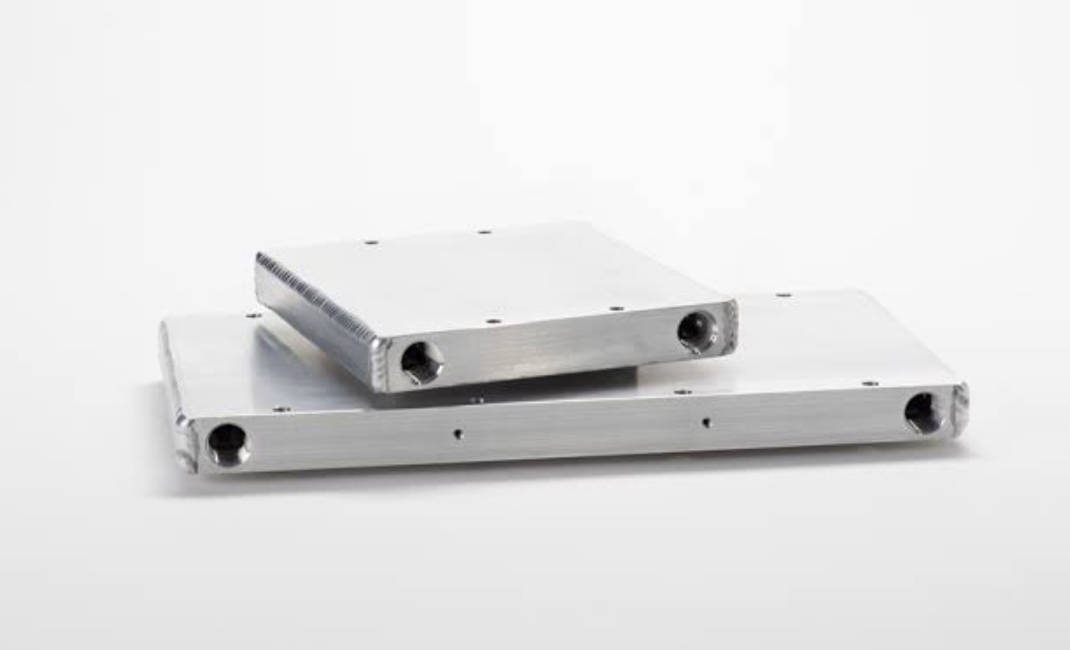
Choosing a coolant distribution unit (CDU) for direct-to-chip cooling starts with the cold plates, not the CDU’s rated cooling capacity. A 1 MW CDU may have enough heat exchange capacity on paper but still fail to deliver the flow required by the cold plate loop. The problem is usually hydraulic: the pump cannot overcome the combined resistance of cold plates, manifolds, hoses, and fittings.
The selection process should follow the actual cooling loop. Start with the cold plate heat load and target coolant temperature rise (ΔT). Calculate the required flow, establish the total pressure-drop budget, and check the pump curve against the selected coolant. Then verify material compatibility, operating phase, redundancy, and control requirements.
This guide explains how to translate cold plate specifications into CDU requirements. It covers the calculations, design constraints, and supplier information needed to avoid a common mistake: buying a CDU with the right kW rating but the wrong hydraulic performance.
Why CDU Selection Starts on the Cold Plate Side, Not the CDU Datasheet
A CDU datasheet typically highlights cooling capacity, maximum flow, pump head, and heat exchanger performance. These figures are useful, but none of them tells you whether the unit can support your specific cold plate loop. That can only be determined after the system requirements are defined.
The mismatch problem: A 1 MW CDU that cannot deliver the required flow
Consider a rack with a 1 MW liquid-cooling load. A supplier proposes a 1 MW CDU, and the cooling capacity appears to match. But suppose the cold plates require 1,500 L/min at the design ΔT, while the combined resistance of the cold plates, manifolds, hoses, and quick disconnects exceeds the pump’s available pressure at that flow.
The CDU cannot maintain the required circulation. Coolant flow falls below the design value, heat removal becomes insufficient, and component temperatures may rise. The unit is not necessarily undersized in terms of heat exchange capacity. Its pump simply cannot meet the hydraulic demand. Rated kW and pump performance must be evaluated separately.
What system requirements actually mean
Before comparing CDU models, define the conditions the secondary cooling loop must maintain: the flow rate needed to remove the rack’s heat load at the target ΔT; the pressure drop created by cold plate channels, manifolds, hoses, fittings, valves, and filters; the coolant type, glycol concentration, viscosity, operating temperature, and wetted-material compatibility; whether the cold plates use single-phase liquid or a two-phase refrigerant; and the level of cooling availability required during pump failure, maintenance, or power interruption.
These requirements determine the CDU’s operating envelope. They should be established before a supplier recommends a model.
The three inputs every CDU supplier should request
Three groups of cold plate and loop data form the starting point for a meaningful quotation:
- Cold plate pressure-drop curve: The pressure drop at different flow rates, measured or validated for the intended coolant and temperature.
- Total loop resistance: The estimated pressure losses across cold plates, manifolds, hoses, quick disconnects, and other components.
- Coolant and phase constraints: Fluid composition, wetted materials, temperature range, and whether the system operates in single-phase or two-phase mode.
Without these inputs, a CDU quotation based only on rack power cannot establish whether the proposed pump and heat exchanger will work under actual operating conditions.
Flow Rate: From Cold Plate Heat Load to CDU Pumping Capability
Once the system’s thermal requirements are clear, calculate how much coolant must circulate through the loop. Rack power provides the heat-load figure, but the target coolant temperature rise determines how much flow is needed to carry that heat away.
The flow-per-kW rule and why it is only a starting point
A preliminary reference for direct-to-chip liquid cooling is approximately 1.5–3.0 L/min per kW. Higher-density systems may use the upper end of this range. However, this range is only useful for early estimates. It does not replace a heat-balance calculation. Two racks with the same 200 kW load may need different flow rates if one operates at a 5K coolant temperature rise and the other at 10K.
The basic relationship is:
Q = m × Cp × ΔT
Where Q is heat removed (W), m is coolant mass flow rate (kg/s), Cp is coolant specific heat capacity (J/kg·K), and ΔT is the coolant temperature rise across the cold plates (K).
Cold plate ΔT and the real flow requirement
For preliminary calculations using PG25, the following approximation can be used:
Flow per kW ≈ 15 ÷ ΔT (L/min per kW)
At a 5K temperature rise, the estimate is 3.0 L/min per kW. At 8K, it falls to approximately 1.88 L/min per kW. At 10K, it is approximately 1.5 L/min per kW. Lower ΔT requires more coolant circulation; higher ΔT reduces flow demand but may increase coolant outlet temperatures and create thermal limitations for downstream components. Use this relationship for initial sizing only. Final calculations should use the actual density and specific heat capacity of the selected coolant at the design operating temperature.
Series vs. parallel cold plate layouts
The total rack flow is not determined by heat load alone. The way cold plates connect to the distribution network also affects pump requirements and flow balance.
In a series arrangement, coolant passes through one cold plate and then enters the next. The same flow travels through every plate, but pressure drops accumulate along the path, and coolant temperature increases as it moves through successive components. In a parallel arrangement, the supply manifold divides coolant among multiple branches. Total system flow is the sum of the individual branch flows. Each branch has its own hydraulic resistance, so differences in channel geometry, hose length, or fitting restrictions can cause uneven flow distribution.
A rack with eight parallel cold plate branches needs enough total flow for all eight branches while maintaining acceptable flow in each one. A high total flow reading at the CDU does not prove that every cold plate receives its required share. The connection layout must therefore be included in both the flow calculation and the pressure-drop budget. See parallel vs. series flow channel design for a more detailed comparison.
Flow-sizing table: Rack power and required coolant flow
The table below converts rack heat load into estimated total flow at three common design temperature rises. It provides a starting point for discussions with CDU suppliers.
| Rack Heat Load | 5K ΔT | 8K ΔT | 10K ΔT |
|---|---|---|---|
| 50 kW | 150 L/min | 94 L/min | 75 L/min |
| 100 kW | 300 L/min | 188 L/min | 150 L/min |
| 200 kW | 600 L/min | 375 L/min | 300 L/min |
| 500 kW | 1,500 L/min | 938 L/min | 750 L/min |
| 1 MW | 3,000 L/min | 1,875 L/min | 1,500 L/min |
Note: Estimates use approximately 15 L/min per kW at a 1K temperature-rise reference for PG25. Actual flow requirements depend on coolant properties and operating conditions.
After calculating the required flow, the next question is whether the CDU pump can deliver it through the installed loop. This requires a separate pressure-drop calculation.
Pressure Drop and Head Budget: What the CDU Pump Actually Has to Overcome
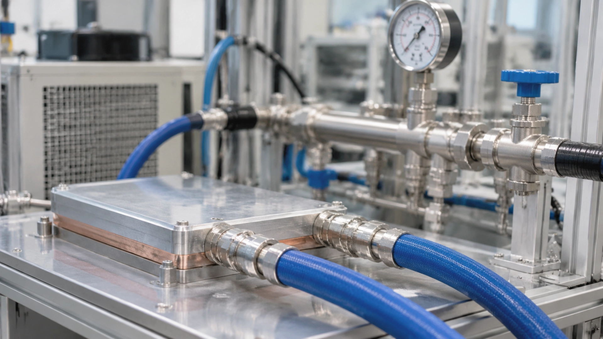
A pump must deliver the required flow against the resistance of the entire secondary loop. Looking at the cold plate pressure drop alone is not enough. Hoses, manifolds, quick disconnects, filters, and valves all consume part of the available pump head.
The full loop pressure budget
For a typical direct-to-chip system, the pressure-drop budget should include cold plate internal channels, supply and return manifolds, flexible hoses and rigid piping, quick disconnects and isolation valves, and filters or other inline components:
ΔP_total = ΔP_cold plates + ΔP_manifolds + ΔP_hoses + ΔP_fittings + ΔP_filters
Each value must correspond to the actual flow through that component. The main supply hose carries the total rack flow, while an individual cold plate branch carries only its allocated branch flow. Applying the total rack flow to every component would produce an incorrect budget.
Typical pressure-drop references and what they tell you
Reference values help engineers identify where hydraulic restrictions may become significant. They should not be treated as fixed design allowances. For example, an H200-class cold plate may have a pressure drop below approximately 18 kPa at around 8 L/min, depending on its internal channel design and test conditions. Hose and fitting assemblies may introduce losses in the region of 5 psi, but the actual value depends on hose length, internal diameter, flow rate, and connection geometry.
A CDU specification may also reference approximately 1 bar of external secondary-side pressure requirement. Before using that figure, confirm exactly what the supplier includes in the rating. It may refer to an available external pressure allowance rather than the pressure loss of the CDU’s internal components. If the cold plates consume 18 kPa but the hoses, manifolds, and quick disconnects consume considerably more, redesigning the cold plate channels alone may not solve the system’s hydraulic problem.
Engineers can often reduce the total pressure drop by increasing restrictive hose diameters, shortening unnecessary pipe runs, selecting lower-loss fittings, or adjusting the manifold layout. See how to reduce pressure drop in liquid cold plate design for related design considerations.
Why a single CDU rated-head value is insufficient
A pump’s maximum head is usually measured at or near zero flow. It does not tell you how much pressure the pump can provide at the required operating flow. Ask the CDU supplier for the complete pump performance curve, then check the operating point against the system resistance curve. The selected pump must deliver the target flow at a differential pressure greater than or equal to the calculated loop requirement.
Coolant properties must also match the calculation. PG25 has different viscosity and density from pure water, and these properties change with temperature. A pump curve based on water should not be accepted as proof of performance with PG25 unless the supplier provides validated corrections or test data. Do not select a pump using only its maximum flow or maximum head rating.
Use the following worksheet to collect the component losses before requesting a CDU quotation, keeping design flow and test conditions consistent wherever possible.
| Loop Component | Design Flow | Pressure Drop | Data Source |
|---|---|---|---|
| Cold plates | Target branch flow | _____ kPa | Cold plate ΔP curve |
| Manifolds | Total or branch flow | _____ kPa | Manifold calculations |
| Hoses and piping | Actual section flow | _____ kPa | Pipe loss calculation |
| Quick disconnects and fittings | Actual connection flow | _____ kPa | Component datasheets |
| Filters and valves | Actual section flow | _____ kPa | Component datasheets |
| Design margin | — | _____ kPa | Engineering allowance |
| Total loop requirement | Design flow | _____ kPa | Calculated total |
Once the total is calculated, compare it with the CDU pump’s available differential pressure at the required flow. Include an appropriate engineering margin, but do not use an arbitrary margin to compensate for missing component data.
Coolant and Material Compatibility: The Constraint That Eliminates CDUs Before Sizing Even Starts
Hydraulic performance is only one part of CDU selection. The coolant must also be compatible with every wetted component in the system. A CDU with the right pump curve may still be unsuitable if its heat exchanger, seals, or pump materials cannot tolerate the specified fluid.
Glycol concentration, conductivity, and sensor compatibility
Single-phase cooling systems often use propylene glycol-water mixtures such as PG25. The glycol concentration affects viscosity, density, specific heat capacity, and thermal conductivity. Increasing glycol concentration generally raises viscosity and reduces specific heat capacity. The pump may therefore need to work harder to maintain the same flow, while the coolant carries less heat per unit mass for a given temperature rise.
Conductivity also needs attention. Some cooling systems specify electrical conductivity limits to protect sensitive equipment and maintain fluid quality. Confirm whether the CDU’s conductivity sensors, flow meters, seals, and other wetted components are compatible with the chosen coolant and its additives.
Aluminum vs. copper cold plates
Material compatibility must be checked across the entire loop, not just at the cold plate. Aluminum and copper are both common cold plate materials, but combining dissimilar metals in the same coolant circuit can introduce galvanic corrosion risks. The outcome depends on the coolant chemistry, corrosion inhibitors, metal combination, and operating conditions. Check the materials used in the CDU heat exchanger, pump housing, manifolds, fittings, and cold plates before approving the fluid specification.
For a closer comparison of these two materials, see aluminum vs. copper liquid cold plates.
Two-phase refrigerants: Hermeticity, moisture, and non-condensable gases
Two-phase systems introduce a different compatibility problem. The refrigerant circuit must remain sealed under its specified pressure and temperature conditions. Seals, joints, valves, and other wetted components must be suitable for the selected refrigerant.
Moisture and non-condensable gases can interfere with heat transfer and system operation. This makes cleanliness, evacuation, and leak-tight assembly important parts of the manufacturing and commissioning process. For refrigerant-based cold plates, helium leak testing can help verify the integrity of components and assembled circuits. See cold plate helium leak detection for details on the testing process.
At this stage, the coolant specification and operating phase should already be defined. They determine which CDU configurations can be considered in the next selection step.
Single-Phase vs. Two-Phase Cold Plates: A Branching Logic, Not a Feature Comparison
Single-phase and two-phase cooling require different approaches to fluid circulation, heat transfer, and control. Treating them as simple product categories can lead to incorrect pump and heat exchanger specifications. The operating phase should instead determine which engineering questions come first.
Single-phase: Flow and pressure dominate CDU sizing
In a single-phase system, the coolant remains liquid as it passes through the cold plate. It absorbs heat and leaves at a higher temperature than it entered. The sizing process follows the heat balance: calculate the required flow from the heat load and target ΔT, establish the pressure drop across the complete loop, and select a CDU pump that can meet both requirements.
The heat exchanger must also maintain the required coolant supply temperature. Its performance depends on facility water temperature, coolant flow, fluid properties, and the heat exchanger’s approach temperature. For a conventional direct-to-chip system using PG25, the main selection questions are usually:
- Can the CDU deliver the required flow at the calculated loop pressure drop?
- Can its heat exchanger maintain the target supply temperature at the available facility water conditions?
- Are the pump, heat exchanger, and wetted materials compatible with PG25?
Two-phase: Refrigerant compatibility and hermetic sealing take priority
In a two-phase cold plate, the working fluid changes phase as it absorbs heat. Heat removal depends on saturation temperature, operating pressure, latent heat, and refrigerant circulation conditions. The conventional single-phase flow-per-kW calculation is no longer sufficient. Engineers must establish the refrigerant mass flow, operating pressure range, phase distribution, and heat rejection requirements for the specific architecture.
Component compatibility also becomes more restrictive. Pumps, heat exchangers, valves, seals, and sensors must be designed for the selected refrigerant and its operating conditions. Moisture control and leak tightness need to be addressed during component selection and system assembly. Control logic must account for refrigerant pressure and phase stability rather than relying only on conventional liquid supply temperature and flow measurements.
CDU selection decision table
The following table summarizes which specifications need to change when moving from a single-phase to a two-phase cold plate system.
| Specification Item | Single-Phase System | Two-Phase System |
|---|---|---|
| Heat removal | Sensible heat and coolant ΔT | Phase change and latent heat |
| Flow calculation | Heat load, Cp, and target ΔT | Refrigerant mass flow and phase-change conditions |
| Pump requirements | Flow rate and loop pressure drop | Refrigerant-specific circulation requirements |
| Heat exchanger | Approach temperature and heat transfer capacity | Refrigerant condensation or evaporation requirements, depending on architecture |
| Fluid compatibility | Glycol concentration and wetted materials | Refrigerant compatibility and seal integrity |
| Leak control | Liquid containment and leak detection | Hermeticity, moisture, and non-condensable gas control |
| Control strategy | Supply temperature, flow, and pressure | Pressure, saturation conditions, and phase stability |
| Common requirements | Thermal capacity, system integration, alarms, serviceability, and reliability | |
A conventional single-phase CDU should not be assumed to support a two-phase refrigerant circuit. Some systems use an intermediate heat exchanger to separate the two circuits, but that requires a purpose-designed architecture and separate performance verification.
Redundancy, Control, and Serviceability: What the Cold Plate Loop Cannot Tolerate
After flow, pressure, and coolant requirements are defined, the next question is whether the system can maintain cooling during a fault or maintenance operation. A CDU that meets the normal operating point may still be unsuitable if a single pump failure interrupts coolant circulation to every cold plate.
N+1 vs. 2N: Match redundancy to the thermal load
N+1 redundancy provides one additional component or unit beyond the capacity required for normal operation. If one pump fails, the remaining equipment can maintain the required operating condition, provided the standby capacity and changeover controls are correctly designed. In a 2N architecture, two independent systems can each support the full required load. This offers greater separation but requires more equipment, installation space, and investment.
The decision should reflect the consequences of cooling interruption. A high-density accelerator rack with strict thermal limits may justify a different redundancy level from a lower-density system with more tolerance for temporary load reduction.
Control: Protecting cold plate supply temperature
The CDU should maintain supply temperature within the cold plates’ permitted operating range. If the coolant enters too warm, the temperature difference available for heat transfer decreases. If it becomes too cold, surfaces may fall below the surrounding air’s dew point and create condensation risks.
Confirm the CDU’s temperature control accuracy, flow and pressure monitoring, alarm thresholds, and response to abnormal conditions. The control system should detect a loss of circulation or an unexpected supply temperature change before the cold plates exceed their operating limits.
Serviceability: Isolation without unnecessary cooling interruption
Maintenance access should be considered before the piping layout is finalized. Filters need accessible replacement points. Pumps and valves should be serviceable without dismantling large sections of the distribution network.
Where continuous cooling is required, the system should allow a failed or serviceable component to be isolated while maintaining the required flow through the remaining circuit. Quick disconnects help simplify connections, but they do not replace a properly designed isolation and redundancy strategy.
The CDU RFQ Parameter Pack: What to Send Suppliers (and What to Ask Back)
Once the thermal, hydraulic, and compatibility requirements are defined, they can be converted into a structured request for quotation (RFQ). The purpose is to give every CDU supplier the same operating conditions and require evidence that the proposed unit can meet them.
Cold plate-side inputs
Start with data that defines the cold plate’s thermal performance and hydraulic resistance. These values should come from engineering calculations or verified test results.
- Total liquid-cooled heat load and required flow per cold plate, branch, and complete rack.
- Cold plate pressure-drop curve at the target flow.
- Target coolant ΔT and permitted supply and return temperatures.
- Coolant type, glycol concentration, operating phase, and cold plate material.
- Series or parallel connection layout.
Loop-side inputs
The CDU supplier also needs the distribution and facility conditions. These determine how much pump head is required and whether the heat exchanger can reject the rack’s heat load.
- Manifold, hose, piping, fitting, and quick disconnect pressure losses.
- Calculated total secondary-side pressure drop.
- Facility water supply temperature and available flow conditions.
- Required heat exchanger capacity and coolant supply temperature.
- Redundancy target, installation space, electrical supply, and communication interfaces.
Evidence to request from the CDU supplier
Do not accept a rated cooling capacity as the only proof of suitability. Ask the supplier to provide the following information for the proposed operating conditions:
- Pump performance curve: Flow versus differential pressure using the specified coolant concentration and operating temperature.
- Heat exchanger performance: Available cooling capacity and approach temperature at the specified facility water supply temperature and design flow.
- Operating envelope: Minimum and maximum flow, pressure, temperature, and coolant compatibility limits.
- Control and alarm documentation: Temperature control accuracy, pressure and flow monitoring, alarm thresholds, and communication interfaces.
- Redundancy and maintenance details: Standby capacity, changeover behavior, filter replacement, pump isolation, and service access.
A complete RFQ package makes quotations easier to compare. More importantly, it reveals whether the proposed CDU can meet the actual operating point rather than simply matching the rack’s nominal power.
If cold plate performance data is not yet available, obtain it before finalizing the CDU specification. Review brazed liquid cold plates design data and liquid cold plate reliability testing results to identify the flow, pressure-drop, and material information needed for system integration.
Common Mismatches and FAQs
Most CDU selection problems come from treating individual ratings as complete system specifications. The following examples highlight where that approach breaks down.
Common CDU selection mistakes
1. The CDU is rated for the required kW, but cannot deliver the required flow.
Cooling capacity and pump performance are separate requirements. Check the flow rate at the calculated pressure drop, not just the CDU’s maximum flow rating.
2. The pump head looks sufficient, but the calculation uses water instead of PG25.
PG25 has different viscosity from water, which affects loop resistance and pump performance. Verify the pump curve using the actual coolant concentration and temperature.
3. Redundancy is postponed until installation.
Adding redundancy later may require changes to pumps, manifolds, valves, piping, and controls. Define the required availability before the cooling architecture is finalized.
Frequently asked questions
What flow rate should I specify for a direct-to-chip CDU?
Calculate it from the total heat load, coolant properties, and target ΔT. For preliminary PG25 sizing, use approximately 15 ÷ ΔT L/min per kW, then verify the result using actual fluid properties.
Does glycol concentration change CDU sizing?
Yes. Glycol concentration affects viscosity, density, and specific heat capacity. These changes influence pump requirements and heat exchanger performance.
Can a two-phase CDU run single-phase cold plates, or vice versa?
Not automatically. The fluid circuit, pressure range, pump, heat exchanger, and controls must be compatible. An intermediate heat exchanger can separate different circuits in some system architectures.
What pressure-drop data should I request from my cold plate supplier?
Request a pressure-drop-versus-flow curve with the coolant type, concentration, temperature, and test conditions clearly stated. A single pressure-drop figure without its corresponding flow rate is insufficient for pump selection.
Conclusion: Size the Loop, Then Select the CDU
Start CDU selection with the cold plate’s thermal and hydraulic requirements. Use the heat load and target ΔT to calculate flow, combine the pressure losses across the complete loop, and verify the pump curve using the actual coolant. Then confirm heat exchanger performance, material compatibility, operating phase, redundancy, and control requirements.
Send these values to CDU suppliers as a structured RFQ and request performance evidence at the specified operating point. The goal is not simply to buy a CDU with enough rated kW. It is to select a unit that delivers the required flow, pressure, and coolant temperature throughout the real operating conditions of the cold plate system.