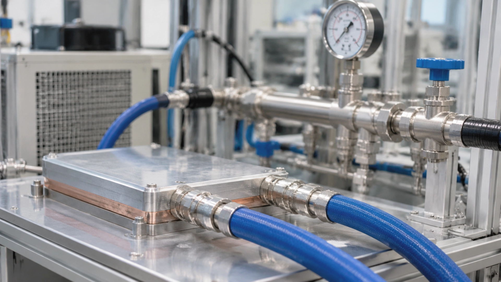
Liquid cooling leak detection in data centers works best when four actions are connected: detect the leak, locate its source, isolate the affected circuit, and verify the system before restarting it. Sensors alone cannot complete this process. Facility teams also need coverage across cold plates, rack manifolds, coolant distribution units (CDUs), and facility piping, along with clear inspection and response procedures.
A loose quick-disconnect fitting can release coolant inside a server rack. A damaged seal can cause slow seepage around a CDU pump. A failed pipe connection can affect an entire cooling loop. These incidents require different detection methods and isolation procedures. This guide explains how to build a program around four monitoring layers, choose between direct sensors and indirect signals, prevent common leak sources, and establish a response procedure that protects equipment without unnecessarily shutting down unaffected circuits.
Why Liquid Cooling Leak Detection Needs a Program, Not Just a Sensor
Liquid cooling systems distribute coolant through multiple components and connection points. A sensor installed beneath a CDU cannot detect every leak inside a rack, and a pressure alarm cannot identify the exact location of a damaged fitting.
The risk profile: fluid near power, high-density racks, and CDU loops
In direct-to-chip cooling, coolant travels through cold plates for GPU cooling mounted close to CPUs, GPUs, and other electronic components. Hoses and manifolds distribute fluid across the rack, while CDUs regulate circulation between secondary and primary loops. The consequences of a leak depend on where coolant escapes, how quickly it spreads, and whether the affected equipment remains energized. A slow drip beneath a manifold requires a different response from a pressurized hose failure near a server power connection.
What “good” looks like: detect, locate, contain, and respond
A leak detection program should connect four operational steps:
- Detect: Identify liquid at the source or recognize operating conditions that indicate a possible leak.
- Locate: Identify the affected rack, fitting, pipe section, or cooling circuit.
- Contain: Stop or limit coolant flow and prevent fluid from reaching adjacent equipment.
- Respond: Repair the fault, verify system integrity, and authorize a controlled restart.
For example, a sensing cable beneath a rack manifold may detect moisture, while CDU pressure and flow readings help operators identify the affected circuit. Isolation valves then allow the team to stop coolant delivery to the damaged section without shutting down the entire cooling system, provided the system design supports that approach.
Where most programs fail: coverage gaps, false alarms, and unclear ownership
Three problems commonly undermine these procedures. Incomplete coverage leaves sensors in the mechanical room while quick-disconnect fittings and rack manifolds go unmonitored. Uncontrolled alarms from condensation, cleaning water, or damaged sensing cables trigger repeated notifications. Unclear ownership means operators receive an alarm but do not know who verifies it, who controls the isolation valves, or who approves the restart.
Adding more sensors will not fix an undefined response process. Every monitored area needs an assigned owner, a documented alarm route, and a procedure for confirming and handling the event.
A Four-Layer Detection Architecture: Chip/Rack/CDU/Facility
The first step in designing coverage is to map the coolant distribution system from the server component to the facility cooling loop. Dividing it into four layers makes it easier to identify leak locations, select appropriate sensors, and assign maintenance responsibilities.
Component and cold-plate layer
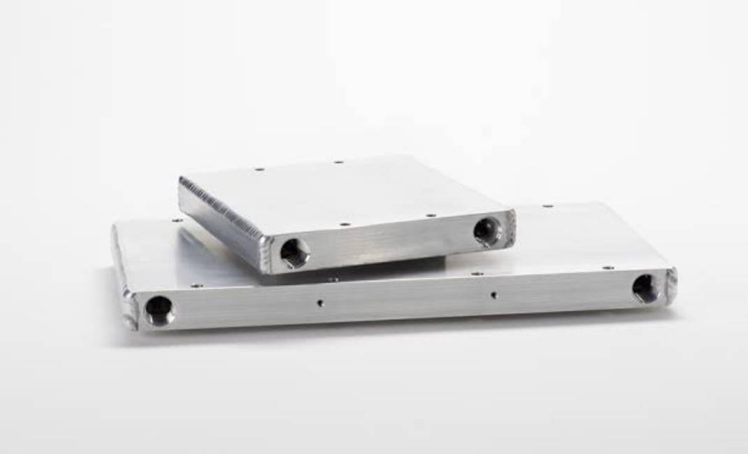
The component layer covers cold plates—many of them brazed liquid cold plates—internal coolant passages, seals, and connections close to processors. Where accessible, position moisture sensors near fittings and likely drip paths; for internal passages that cannot be monitored directly, use pressure, flow, and temperature data as supporting indicators. Sensor placement must not obstruct server servicing, and hardware teams should define how technicians inspect coolant connections when replacing a server or removing a cold plate.
Rack, manifold, and quick-disconnect layer
The rack layer covers supply and return manifolds, branch connections, flexible hoses, and quick-disconnect couplings. These connections deserve particular attention after maintenance: a quick disconnect that is not fully engaged may appear connected while its internal seal is improperly seated. Leak detection cables can run beneath manifolds or along defined drip paths, and point sensors work well beneath individual connections or inside drip trays. The monitoring system should identify the affected rack or distribution section rather than reporting only a general water alarm.
CDU and secondary loop layer
The CDU introduces pumps, valves, filters, heat exchangers, expansion vessels, and secondary-loop connections as potential leak points. Install moisture sensors around accessible joints and equipment bases, and monitor pressure, flow, temperature, and pump status for operating changes that may indicate a developing problem. An unexplained pressure drop combined with an abnormal flow reading may indicate fluid loss, but pump speed changes and valve operations can produce similar signals, so operators should check the CDU operating state before classifying the event as a confirmed leak.
Room, primary loop, and facility layer
The final layer extends monitoring into mechanical rooms, primary-loop piping, floor penetrations, and facility-level cooling distribution. Use sensing cables along accessible pipe routes and point sensors near pumps, valves, and heat exchangers. Facility engineering teams typically manage primary-loop monitoring and building-level isolation, while data center operations teams coordinate these actions with rack and CDU owners.
Four-layer leak detection coverage matrix
The following matrix connects each monitoring layer with its typical leak points, detection methods, and response owner. It can serve as a starting point for a site-specific coverage map.
| Layer | Typical Leak Points | Direct Detection | Indirect Signals | Primary Response Owner |
|---|---|---|---|---|
| Component / Cold Plate | Cold plates, seals, hose connections, internal passages | Local moisture sensors, drip sensors | Pressure, flow, temperature deviations | Server hardware and cooling maintenance teams |
| Rack / Manifold | Manifolds, quick disconnects, hoses, branch fittings | Sensing cables, point leak sensors | Branch flow and pressure changes | Rack operations and liquid cooling maintenance teams |
| CDU / Secondary Loop | Pumps, valves, heat exchangers, filters, connections | Point moisture sensors, cable sensors | Loop pressure, flow, temperature, pump status | CDU and cooling system engineers |
| Facility / Primary Loop | Distribution pipes, mechanical rooms, valves, floor penetrations | Area sensing cables, floor sensors | System pressure, flow, supply-return temperature | Facility engineering and building operations |
These assignments should be adapted to the site’s organizational structure. The important requirement is that every alarm has an owner and every isolation action has an authorized operator.
Detection Methods Compared: Direct Sensors, Indirect Signals, and Validation Tests
The coverage matrix shows where each method fits. This section explains what each method can and cannot do. Three categories serve different purposes: direct sensors detect liquid, indirect signals identify abnormal system behavior, and validation tests check component integrity before equipment enters service or returns from maintenance.
Contact/resistive sensors and sensing cables: where they fit
Contact-based sensors detect liquid when moisture reaches an exposed sensing element; resistive designs measure changes in resistance or conductivity between contacts when liquid bridges them. Point sensors suit localized areas such as CDU pump bases, valve connections, and drip trays, but liquid must reach the sensor before it can respond. Sensing cables extend detection along a defined route and may identify the affected section, but installation matters as much as selection: a cable placed above the likely drip path may never contact leaked coolant. Routes should account for floor slopes, equipment layout, cleaning activity, and maintenance access.
Humidity, temperature, pressure, and flow: early warning and false-positive control
Indirect monitoring helps identify changes that may occur before a leak becomes visible, but these measurements do not confirm the presence of coolant. A humidity increase may indicate moisture accumulation, yet condensation and ventilation changes produce similar readings; a pressure decline may indicate fluid loss—sometimes reflecting pressure drop in cold plate flow channels rather than a leak—yet pump operation, valve movement, and thermal expansion must also be considered. These signals become more useful when evaluated together: a pressure drop accompanied by an unexpected flow imbalance and a local moisture alarm provides stronger evidence than a brief pressure fluctuation alone. Alarm logic should also recognize normal operating transitions so that pump startup or scheduled valve adjustments do not generate unnecessary notifications.
Tracer gas, pressure decay, and vacuum testing: for CDU and component validation
Real-time sensors monitor operating equipment; integrity tests verify whether components and assemblies meet specified leak-tightness requirements before installation or after repair. Helium leak detection identifies leakage through joints, seals, or internal passages under controlled conditions and is useful when sensitive verification is required for cold plates, heat exchangers, and CDU assemblies. Pressure decay testing measures pressure changes in a sealed volume over a defined period, but temperature changes, material expansion, test volume, and instrument accuracy can affect the result. Each method requires documented test conditions and acceptance limits, and a CDU that passes a factory leak test still needs operational monitoring because transportation, installation, and later maintenance can introduce new leak points.
Method selection matrix by scenario
Use the following comparison to match each method to its intended application. The key distinction is whether the goal is to detect liquid during operation, identify an abnormal condition, or verify equipment integrity.
| Method | Suitable Layer | Main Advantage | Limitation | Not Ideal For |
|---|---|---|---|---|
| Point moisture sensor | Rack, CDU, facility | Direct detection at localized collection points | Limited physical coverage | Long pipe routes without multiple sensors |
| Leak detection cable | Rack, CDU, facility | Continuous coverage along selected routes | Requires correct routing and maintenance | Locations without predictable liquid contact paths |
| Humidity monitoring | Rack, room, facility | Environmental context and moisture trends | Cannot reliably distinguish coolant leaks from other moisture sources | Confirming an individual fitting leak |
| Temperature monitoring | Component, rack, CDU | Identifies thermal abnormalities | Indirect and affected by operating conditions | Direct leak confirmation |
| Pressure monitoring | Rack, CDU, facility | Identifies abnormal circuit pressure behavior | Requires operating-state and temperature context | Locating small leaks without supporting measurements |
| Flow monitoring | Rack, CDU, facility | Identifies abnormal coolant distribution | Affected by pump and valve control changes | Detecting every small external seepage event |
| Tracer gas testing | Component, CDU | Sensitive integrity verification | Requires specialized equipment and procedures | Continuous in-service monitoring |
| Pressure decay testing | Component, CDU, piping | Practical verification of sealed test volumes | Temperature and volume effects influence results | Real-time leak localization |
For most facilities, the practical combination is direct moisture detection at high-risk locations, pressure and flow monitoring for system-level warnings, and integrity testing during manufacturing and maintenance.
Root Causes and Prevention: What to Inspect Before You Detect
Most preventable leaks involve connections, seals, fluid compatibility, maintenance work, or cold plate manufacturing quality. Inspecting these areas reduces the chance of a leak and makes it easier to identify problems before coolant reaches sensitive equipment.
Fittings, seals, quick disconnects, and tubing
Inspect quick-disconnect couplings, O-rings, threaded fittings, clamps, and flexible hoses for visible moisture, residue, cracks, corrosion, and deformation. A hose routed under tension may gradually pull against a fitting, a twisted hose can place additional stress on its connection, and a damaged O-ring may leak even when the coupling appears properly installed. After server replacement or rack maintenance, verify that quick disconnects are fully engaged and sealing surfaces are clean, following the connector manufacturer’s installation requirements rather than relying on visual inspection alone.
Corrosion, fluid chemistry, and glycol concentration
Coolant chemistry affects the condition of wetted components. Incompatible materials, contamination, depleted corrosion inhibitors, and unsuitable fluid mixtures can contribute to corrosion and deposits. Check glycol concentration against the coolant manufacturer’s specified range, and investigate cloudiness, suspended particles, unexpected discoloration, and deposits. Clear coolant is not proof of good fluid condition, so use appropriate fluid analysis when the system requires it.
Installation and service-induced leaks
Leaks can appear immediately after installation or several operating cycles after maintenance. Common causes include incorrect fitting torque, damaged sealing surfaces, incomplete quick-disconnect engagement, and contamination introduced during assembly. Maintenance procedures should specify approved tools, connection sequences, torque requirements where applicable, coolant handling, and post-service inspection. Do not return a serviced cooling circuit to normal operation until the required leak or pressure integrity checks have passed.
A 10-point pre-detection inspection checklist
Use this checklist during scheduled inspections and after work on the cooling system.
- Inspect accessible cold plate connections for moisture and dried coolant residue.
- Check O-rings and sealing surfaces whenever connections are disassembled.
- Verify that quick-disconnect couplings are fully engaged.
- Look for kinked, twisted, cracked, or mechanically stressed hoses.
- Inspect manifolds, threaded fittings, clamps, and valve connections.
- Check CDU pumps, filters, heat exchangers, and surrounding drip trays.
- Examine pipe supports and mounting points for vibration or mechanical stress.
- Verify coolant concentration and fluid condition against manufacturer specifications.
- Investigate corrosion, particles, deposits, and unexpected fluid discoloration.
- Record maintenance work and complete required integrity checks before restart.
These checks do not replace detection, but they reduce the number of leaks the detection system has to catch.
From Alarm to Action: A Leak Response Playbook
When a leak alarm occurs, operators need to establish whether liquid is present, identify the affected cooling circuit, and determine whether isolation is required. The response must protect personnel and equipment while avoiding unnecessary disruption to unaffected systems.
Alarm triage: weep vs spray vs sensor fault
Classify the event using the available sensor information, visual evidence, and system operating data. Minor seepage—small amounts of moisture or residue around a fitting—may indicate a slow leak; identify the source and assess whether controlled isolation is required. Active spray or significant release—visible coolant discharge or a damaged pressurized connection—requires immediate escalation and the site’s emergency isolation procedure. A possible sensor fault—an isolated alarm without visible moisture—may result from contamination, condensation, damaged sensing cable, or electrical failure; follow the verification procedure before clearing it.
Check the alarm location, nearby equipment, sensor status, and CDU operating data, and record the event time and take photographs when it is safe to do so. If coolant may have reached energized equipment, do not approach or touch the affected area to confirm the leak; follow electrical safety and emergency access procedures.
Isolation and shutdown sequence with residual pressure considerations
Once the affected area is identified, isolate the smallest practical section that can be safely taken out of service.
- Identify the affected zone and cooling dependencies: Determine which rack, branch circuit, CDU, or facility pipe section is associated with the alarm, and identify the servers and cooling paths it supplies, including available redundancy.
- Operate designated isolation valves: Follow the documented valve sequence and control procedure, and stop or reduce coolant delivery to the damaged section when required by the system design.
- Verify isolation: Check valve positions and confirm the expected pressure and flow changes.
- Address residual pressure: Use the manufacturer’s approved procedure to depressurize the isolated section before opening any connection.
Closing an upstream valve does not necessarily remove pressure from the downstream pipe. Coolant may remain trapped between isolation points, inside hoses, or within a component, and loosening a fitting to check for pressure is unsafe. Server shutdown decisions should follow the site’s thermal limits and operational procedures; if cooling capacity is compromised, coordinate load reduction or a controlled shutdown before equipment temperatures exceed their allowable limits.
Containment, cleanup, and restart criteria
After isolation, prevent coolant from spreading into adjacent equipment or floor areas using containment materials compatible with the coolant, and follow the supplier’s cleanup and disposal instructions. Before cleanup begins, assess electrical hazards, slip risks, and personnel exposure requirements. Do not restart the system simply because the visible liquid has been removed. Confirm that:
- The leak source has been identified and repaired or the defective component replaced.
- Required pressure, leak, or integrity tests—including liquid cold plate reliability testing where applicable—have passed.
- Coolant condition and system operating parameters meet specifications.
- Electrical equipment and surrounding surfaces have been inspected and confirmed safe.
- Valves, pumps, sensors, and controls are in their approved operating states.
- Cooling performance remains stable during controlled operation.
Documentation and post-incident review
Record the first alarm time, detection location, affected equipment, operating conditions, isolation actions, repair details, and restart approval. Then determine why the leak occurred: Was an O-ring damaged during maintenance? Did a hose carry excessive mechanical stress? Was corrosion present? Did the sensor detect the leak early enough? Use the findings to update inspection intervals, sensor locations, maintenance procedures, spare-parts planning, and operator training. Each incident should improve the next response.
Monitoring, Inspection, and Fluid Health: Covering Sensor Blind Spots
Not every leak reaches a sensor. Liquid may travel along a cable tray, collect behind equipment, or remain inside an inaccessible enclosure. Routine inspection and coolant monitoring help identify problems that the installed sensor network cannot directly observe.
Recurring visual and thermal inspection
Inspect accessible hoses, manifolds, quick disconnects, CDU connections, drip trays, pipe supports, and floor areas beneath cooling equipment. Look for moisture, dried residue, corrosion, damaged insulation, unusual hose movement, and deposits around fittings—signs that may appear before a sensor triggers an alarm. Thermal inspections can identify abnormal temperature patterns in cooling equipment and distribution lines; compare readings with established operating baselines and investigate unexpected changes. Thermal imaging supports diagnosis but does not confirm an external coolant leak. Inspection frequency should reflect equipment criticality, manufacturer guidance, maintenance history, and previous incidents, with additional checks on connections disturbed during servicing.
Fluid monitoring indicators: glycol concentration, turbidity, and dye
Fluid condition provides another indication of cooling system health. Glycol concentration should be measured using a suitable calibrated method, such as a refractometer when appropriate for the coolant formulation, and compared with the manufacturer’s specified range; concentration affects viscosity and thermal performance, so the correct mixture depends on system design and operating conditions. Turbidity—cloudiness or suspended material—may indicate contamination, corrosion products, precipitation, or fluid degradation. Approved visible or fluorescent tracer dyes can help identify coolant residue during inspections, provided they are compatible with the fluid and system materials; do not add dye without approval from the coolant and equipment manufacturers. Fluid analysis can reveal contamination or degradation, but it cannot replace direct leak detection—a contaminated sample does not identify where coolant is escaping.
Dashboards, alarm thresholds, and integration with BMS/DCIM and CDU controls
A useful monitoring dashboard should show the sensor location, affected equipment, alarm time, current operating conditions, and relevant historical trends. Set thresholds according to equipment specifications and normal operating ranges, accounting for pump speed, valve position, startup sequences, and planned maintenance when configuring pressure and flow monitoring. Where possible, combine related signals: a pressure drop accompanied by abnormal branch flow and a moisture alarm should receive more attention than a brief pressure change during pump startup. Any alarm bypass should have a named owner, a documented reason, and an expiration time.
Leak monitoring should connect with the systems operators already use: CDU controls provide local pump, pressure, flow, temperature, and equipment alarm data; BMS provides visibility into building-level cooling equipment and primary-loop conditions; DCIM connects infrastructure events with rack locations, equipment records, and operational dependencies. Keep direct leak alarms separate from indirect pressure warnings and maintenance notifications so operators know whether a signal confirms liquid contact or simply indicates an abnormal operating condition. Define alarm priority, notification recipients, escalation times, and authorized control actions, and use automatic isolation only where the system design and failure scenarios have been properly evaluated and tested.
Selection and Deployment Checklist for Facility and Ops Teams
Choosing a leak detection system involves more than comparing sensor sensitivity or purchase price. The system must cover the actual coolant routes, operate reliably under site conditions, integrate with existing controls, and remain maintainable throughout its service life.
Coverage and sensor placement
Begin with a physical map of the cooling system, marking cold plate connections, rack manifolds, quick disconnects, CDU components, primary-loop piping, and areas where coolant could collect. For every location, document the detection method, sensor route, coverage limits, accessibility, and responsible maintenance team, and check that sensing cables follow likely drip paths rather than convenient but ineffective routes.
Sensitivity vs false alarms
High sensitivity is useful only when the system can distinguish real leaks from routine environmental moisture and sensor faults. Evaluate response time, sensing coverage, environmental limitations, cable fault detection, and resistance to false alarms. Ask suppliers how their equipment was tested and under what conditions, and avoid relying on unsupported claims such as “instant detection” or “zero false alarms.”
Integration with BMS/DCIM and CDU controls
Check whether the system supports the communication interfaces used by the facility, and review alarm mapping, timestamps, location identification, event history, and behavior during communication failures. A useful alarm should identify the affected rack or equipment area and connect it to the relevant cooling circuit; a generic notification that reports only “water detected” gives operators less information to work with.
Serviceability, lifecycle, and vendor support
Evaluate the cost and effort of maintaining the system after installation, including sensor replacement, cable repair, calibration where required, software updates, spare-part availability, and access to installed equipment. Confirm whether the supplier provides installation documentation, troubleshooting support, maintenance guidance, replacement components, and operator training, and ask how the system behaves during power loss, communication interruptions, and sensor failures.
Deployment checklist
Before accepting a new installation, verify the following items:
- All critical coolant routes and potential leak locations have been mapped.
- High-risk connections have appropriate direct detection coverage.
- Sensor blind spots have been documented and assigned an inspection method.
- Alarm thresholds have been tested under normal operating conditions.
- BMS, DCIM, and CDU integration has been verified.
- Alarm ownership and escalation responsibilities have been assigned.
- Isolation and emergency response procedures have been tested.
- Sensor inspection, replacement, and maintenance schedules are documented, and supplier support, spare-part availability, and lifecycle costs have been reviewed.
Common Pitfalls and FAQs
Before finalizing a deployment, teams should challenge three common assumptions: that sensors provide complete protection, that one test method can handle every requirement, and that leak management belongs to operations alone.
“Sensors are enough”
Sensors cannot monitor every internal connection or prevent mechanical failure, and a leak may travel outside the sensing area. Inspections, maintenance, fluid monitoring, and response procedures remain necessary.
“One method covers all stages”
Direct sensors detect liquid during operation, pressure and flow monitoring identify abnormal system behavior, and tracer gas and pressure decay tests verify component integrity under controlled conditions. These methods complement one another rather than replace one another.
“Leak detection is only an ops issue”
Leak prevention begins with component design, material compatibility, and installation quality. Maintenance teams control connection integrity, while facility and operations teams manage monitoring, isolation, and recovery. Each group has a defined role.
Frequently asked questions
1. What is the best way to detect liquid cooling leaks in a data center?
Use point moisture sensors and sensing cables at high-risk locations, supported by pressure, flow, humidity, and temperature monitoring. The right combination depends on the cooling architecture and the consequences of a leak at each location.
2. How should a CDU be tested for leaks before deployment?
Follow the CDU manufacturer’s documented acceptance procedure. Depending on the design, testing may include pressure decay, tracer gas, or other approved integrity tests. Operational leak monitoring is still required after installation.
3. Does glycol affect liquid cooling leak detection?
Yes. Glycol concentration and coolant formulation can affect conductivity and compatibility with certain sensing technologies. Confirm that the selected sensor is suitable for the actual coolant mixture rather than assuming every water leak detector will respond identically.
4. How can data centers reduce false leak detection alarms?
Place sensors along realistic liquid migration paths and account for condensation, cleaning activity, and normal system transitions. Combine direct moisture detection with operating data where appropriate, and document all maintenance bypasses.
5. Can leak detection systems integrate with BMS and DCIM platforms?
Yes. Many monitoring architectures support integration with BMS, DCIM, and CDU controls through compatible communication interfaces. The integration should preserve alarm location, source, priority, and timestamp.
6. How often should liquid cooling systems be inspected for leaks?
Inspection intervals depend on manufacturer recommendations, equipment criticality, operating conditions, and maintenance history. Check connections after installation and servicing, and increase inspection frequency following a leak or major system modification.
Conclusion: Build a Layered, Lifecycle Leak Detection Program
A reliable data center liquid cooling leak detection program needs four things: coverage across component, rack, CDU, and facility layers; a combination of direct sensors, indirect monitoring, and validation tests; preventive inspections; and a documented response procedure. Start by mapping every critical coolant connection and assigning an owner to each monitored area, then verify alarm behavior, test isolation procedures, and establish clear restart criteria.
The objective is not to install the largest number of sensors. It is to find leaks early, identify the affected circuit, contain coolant safely, and restore cooling without exposing other equipment to unnecessary risk.