
Automotive On-Board Charger Thermal Housing and CNC Surface Quality
Project Summary
Customer problem: An Italian automotive electronics customer was receiving ADC12 die-cast heat sinks with subsurface porosity that became exposed after CNC machining. Visible pinholes on the power-device contact surface pushed the reported scrap/defect rate to 15-20% and disrupted OBC production planning.
JINDU solution: JINDU reviewed the casting flow, injection window, venting and overflow layout, then introduced vacuum-assisted venting, a revised gating/slag-trap strategy, controlled die-casting parameters, X-ray verification and CNC inspection on the critical mounting surface. The work was aligned with JINDU’s die-casting heat sink manufacturing and precision secondary-machining capabilities.
Result: Under the agreed inspection criteria, internal porosity was controlled to ≤2%, CNC-machined contact surfaces showed no visible pore/sand-hole defects during inspection, flatness reached ≤0.08mm, surface roughness reached Ra≤1.2μm, and the production defect rate fell below 1.5%. The customer subsequently transferred the model to JINDU and began introducing two additional OBC heat-sink projects.
Project at a Glance
| Customer Region | Italy |
| Industry | Automotive electronics / on-board charger (OBC) |
| Product | ADC12 die-cast heat sink with CNC-finished contact surface |
| Part Size | 220mm × 150mm × 35mm |
| Surface Requirement | Ra≤1.6μm; no visible pores/pinholes on critical contact area |
| Flatness Requirement | ≤0.10mm |
| Annual Demand | Approx. 8,000 pcs |
| Functional Validation | IP6K9K test required by customer |
| Reported Previous Defect Rate | 15-20% |
| Final Production Defect Rate | <1.5% |
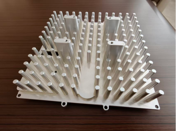
The Failure Mode: Hidden Casting Porosity Exposed by CNC Machining
The customer was not dealing with a cosmetic casting issue alone. The contact surface was a thermal and mechanical interface for power electronics. When CNC milling removed the as-cast skin, subsurface gas/shrinkage pores became visible as pinholes and cavities. Parts with obvious defects could no longer satisfy the specified surface finish and were rejected.
The reported consequences were:
- 15-20% defect/scrap rate after secondary CNC finishing.
- Unstable contact-surface roughness and visual quality.
- Extra sorting, rework and replacement that increased manufacturing cost.
- Schedule risk for the customer’s on-board charger production.
- Concern that uncontrolled internal porosity could also compromise downstream sealing or enclosure reliability if it occurred in critical zones.
Important engineering distinction: A die casting can look acceptable before machining and still contain internal porosity. For this reason, the case was treated as a casting-process and quality-control problem, not as a CNC-programming problem.
Customer Requirements and CTQ Acceptance Criteria
1. Stabilize the High-Pressure Die-Casting Process Window
JINDU adjusted the injection profile, intensification pressure and holding time to reduce air entrapment while maintaining complete filling of the pin-fin and housing geometry. The objective was not simply to raise pressure, but to create a repeatable filling sequence that produced a denser casting in the critical machined region.
2. Add Vacuum-Assisted Venting at the End of Fill
The mold venting concept was upgraded with vacuum assistance at the appropriate end-of-fill area. Removing cavity gas during injection reduces the amount of trapped air that can become internal pores. For a part that will later be CNC-machined, this control is especially important beneath the intended contact surface.
3. Redesign Runner, Overflow and Slag-Trap Locations
The gating and overflow layout was reviewed so that the metal front reached the cavity in a more controlled sequence and displaced gas toward the vent and overflow zones rather than trapping it near the thermal interface. This approach also supports cleaner end-of-fill metal and helps isolate oxides or contaminated material away from critical surfaces.
4. Create an X-Ray Quality Gate Before Mass Production
X-ray non-destructive inspection was added as a process-control gate. First/last pieces from each batch were checked to confirm the internal porosity pattern remained within the agreed acceptance range before full production continued. The ≤2% value in this case refers to the customer/JINDU agreed X-ray evaluation method; porosity percentages are inspection-method dependent and should always be tied to a defined standard, region of interest and acceptance rule.
5. Control the Critical Surface with Precision CNC Finishing
After casting approval, the thermal contact area was finished using precision CNC machining and then checked for visual surface defects, flatness and roughness. This secondary operation aligns with JINDU’s CNC machined heat sink capability, where the machining stage is treated as a CTQ process rather than a simple cosmetic finish.
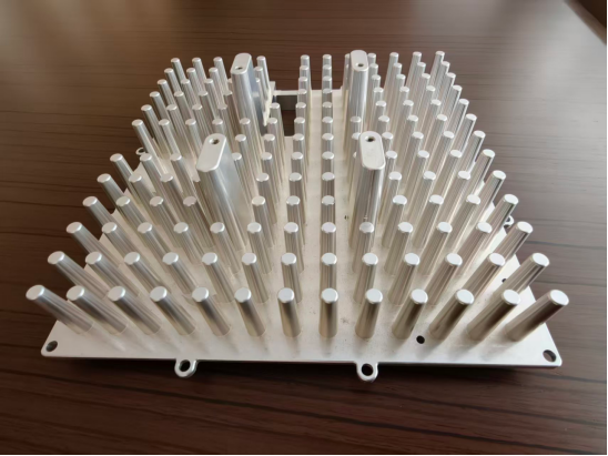
Testing and Validation
The optimized trial lot was validated at both casting and finished-part level. This is important because X-ray inspection alone does not prove the machined interface is acceptable, while surface inspection alone cannot show the internal casting condition.
| Verification | Reported Result | Purpose |
| X-ray non-destructive inspection | Internal porosity ≤2%; no unacceptable concentrated porosity under agreed criteria | Verify internal casting density before machining |
| CNC-finished surface inspection | No visible pores/pinholes on the critical contact surface in accepted parts | Prevent surface-defect escapes |
| Flatness inspection | ≤0.08mm | Meet ≤0.10mm customer requirement |
| Surface roughness | Ra≤1.2μm | Meet Ra≤1.6μm requirement |
| Dimensional capability | Critical dimensions Cpk≥1.67 | Demonstrate repeatability on CTQ dimensions |
| IP6K9K functional test | Customer samples passed | Verify the required ingress-protection performance at assembly/sample level |
Final Result: From 15-20% Defect Rate to Below 1.5%
The optimized die-casting and inspection route reduced the reported production defect rate from the previous supplier’s 15-20% to below 1.5%. Accepted parts met the specified CNC surface quality, flatness and roughness requirements, while samples also passed the customer-required IP6K9K test.
The improvement was significant because it addressed the defect before it reached the final machining operation. Instead of relying on post-machining sorting to remove porous parts, JINDU moved quality control upstream through die-casting process optimization and X-ray verification.
| Metric | Previous Supplier / Requirement | JINDU Result |
| Reported defect rate | 15-20% | <1.5% |
| Visible porosity after CNC | Frequent defects on contact surface | No visible pores/pinholes on accepted inspected surfaces |
| Flatness | Requirement ≤0.10mm | Measured ≤0.08mm |
| Surface roughness | Requirement Ra≤1.6μm | Measured Ra≤1.2μm |
| X-ray porosity | Not adequately controlled by previous process | ≤2% under agreed acceptance method |
| Functional test | IP6K9K required | Samples passed |
| Production status | Supplier-change project | Model transferred to JINDU; two additional OBC heat-sink projects being introduced |
Project Gallery: Final Production Geometry
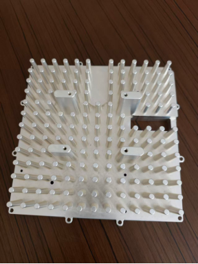 Figure 3. Top view showing the pin-fin field, machined mounting features and open airflow geometry. | 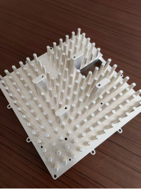 Figure 4. Angled view showing the integrated casting geometry, mounting tabs and machined boss features. |
What Automotive Buyers Should Specify for a Die-Cast Heat Sink with CNC Contact Surfaces
Porosity requirements should be written around the function of the part, not as a vague request for “no pores.” High-pressure die castings inherently require a defined inspection and acceptance method. For OBC, inverter and automotive power-electronics housings, the RFQ should identify the critical machined and sealing zones separately from non-critical cosmetic areas.
- Material grade and required heat treatment, if any.
- Critical machined surface location, machining allowance and Ra requirement.
- Flatness and datum scheme for the power-device interface.
- Defined X-ray inspection zone, image quality level and porosity acceptance criteria.
- Whether vacuum die casting is required for critical regions.
- Leak/IP functional requirements and the exact assembly condition used for validation.
- Cpk requirement for critical dimensions and the sampling/frequency plan.
- Expected annual volume, PPAP/sample approval requirements and traceability needs.
Why JINDU for Automotive Die-Cast Heat Sink Projects?
For applications that combine complex casting geometry with precision thermal interfaces, JINDU can integrate custom die-casting heat sinks, secondary CNC finishing and quality verification within one supplier workflow. This is particularly relevant to OBCs, inverters and other new-energy thermal management applications where mechanical integration, thermal contact quality and production repeatability must be controlled together.
- ADC12/A380 high-pressure die-casting capability for integrated thermal housings.
- Venting, overflow and process-window optimization for porosity-sensitive regions.
- X-ray inspection as a process-control gate for internal casting quality.
- Precision CNC machining for critical thermal contact and mounting surfaces.
- Prototype-to-volume-production support for automotive and power-electronics projects.

