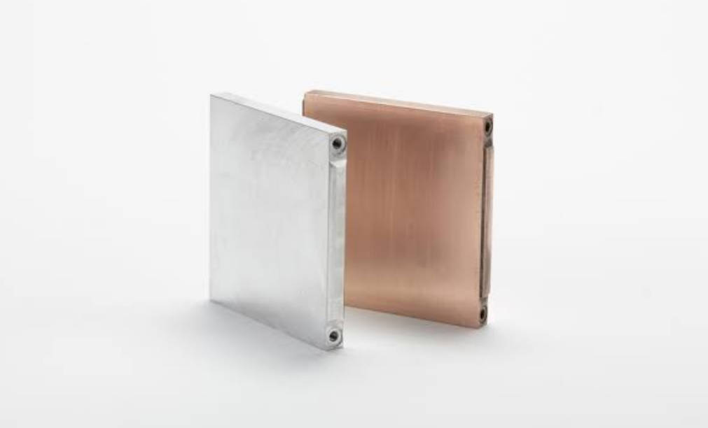
Liquid cold plate thermal testing is the set of measurements used to confirm that a plate moves heat from a heat source to the circulating coolant at the rate its design promises. A reliable cold plate is verified on three fronts: thermal performance, sealing integrity, and flow behavior, before it is trusted in a production system. For research, development, and procurement engineers, testing is the line between a convincing datasheet and a component that survives in the field.
This guide covers the methods engineers actually use, the parameters that matter, the mistakes that undermine results, and how to specify validation requirements when you talk to a liquid cold plate supplier.
What Is Liquid Cold Plate Thermal Testing?
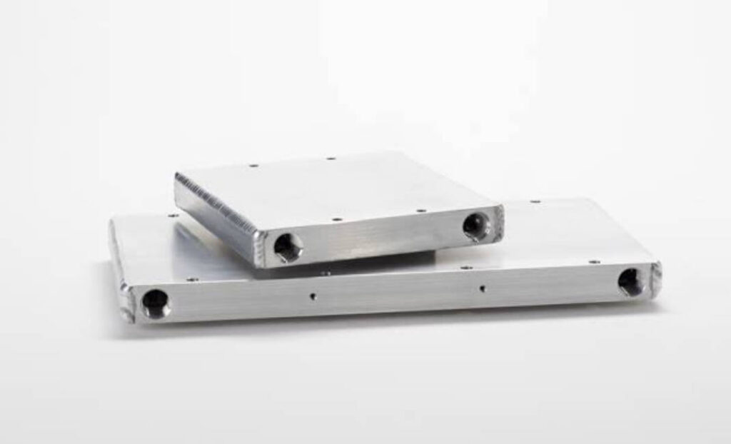
A liquid cold plate is a metal plate with internal channels through which a coolant flows, carrying heat away from a mounted heat source such as an IGBT module, GPU, laser diode, or power amplifier. Thermal testing validates two things: that the plate achieves the promised thermal resistance, and that the assembly will not leak, corrode, or choke the coolant loop under operating conditions.
Internally, plates take several forms: machined or etched channels, brazed or friction-stir-welded (FSW) passageways, or embedded tubes. The manufacturing route affects both performance and how the joints must be tested, so the test plan should reflect the actual construction, not a generic assumption.
Testing is normally performed at the prototype stage and repeated as a lot-acceptance or qualification step before mass production. The goal is not to pass once, but to build a repeatable record that the manufacturing process holds its thermal and mechanical promises.
Why Thermal Testing Matters for Procurement and Reliability
When you buy a cold plate, you are buying a performance guarantee. Without verification, that guarantee is only as good as the supplier’s word.
- De-risks supplier claims. Independent measurement confirms the quoted thermal resistance and pressure drop.
- Prevents field failures. Leak and fatigue testing catch joint defects that a visual inspection misses.
- Sizes the cooling loop correctly. Measured pressure drop tells you what pump and tubing the system actually needs.
- Supports qualification. Some applications require evidence of testing against industry or customer standards before approval.
Skipping validation shifts the risk from the supplier’s test bench to your customer’s field return rate. For high-value or safety-relevant systems, that trade-off is rarely worth it. A plate that fails in a server rack or a power converter does not just get warm; it takes the surrounding electronics with it.
Core Thermal Testing Methods
Thermal Performance Testing
The most common test measures steady-state thermal resistance. A known heat load Q is applied to the plate surface, either by the real device or a simulated heater, while coolant flows at a fixed rate and inlet temperature. Engineers record the hotspot or average surface temperature and the coolant temperature rise, then calculate:
Thermal resistance Rth = ΔT / Q, where ΔT is the temperature difference between the heat source and the coolant, and Q is the heat load in watts. Lower Rth means better cooling per watt.
Infrared thermography is often added to check surface temperature uniformity, because an average number can hide a dangerous local hotspot. Transient methods, which watch how temperature rises and falls over time, can separate the plate’s own resistance from the spreading resistance of the interface material.
Pressure and Leak Testing
Because a leaking plate can destroy the electronics it cools, sealing integrity is tested directly. A hydrostatic pressure test holds the plate above its operating pressure, and a pressure-decay or helium mass-spectrometry test quantifies any leakage. In many production programs, leak testing is performed at 1.5 to 3 times the expected operating pressure, with acceptance based on a maximum allowed decay rate. Plates built by friction stir welding or vacuum brazing are especially scrutinized at the joint line, since that is where a defect would first appear.
Flow Rate and Pressure Drop Testing
Coolant is pushed through the plate at the target flow rate while the pressure drop across the inlet and outlet is measured. This tells you the pumping power the system must supply and whether the internal channel design is practical. A plate that looks excellent thermally can still be rejected if its pressure drop blows the pump budget.
Thermal Cycling and Endurance Testing
Thermal cycling repeatedly heats and cools the plate, or switches the power load on and off, to reveal fatigue, solder or braze joint cracking, and warpage over time. Duration varies by application; endurance programs commonly run from several hundred to a few thousand cycles, depending on the expected duty and the customer’s reliability target. The value is not a single pass, but evidence that performance does not drift as the part ages.
Flow Visualization (Optional)
For development work, dye injection or particle image velocimetry (PIV) can show stagnant zones and uneven flow distribution inside the channels. This is less about pass or fail and more about improving the design before tooling is committed.
Test Setup and Instrumentation
Heat Load Simulation
The heat source should resemble the real device’s power map. A uniform foil heater is convenient but can overstate performance for a device with a concentrated hotspot. Where the real component is available, testing with it gives the most honest result, even if it is slower to set up.
Temperature and Flow Measurement
Surface temperature is typically read with bonded thermocouples or an IR camera; coolant temperature uses immersed sensors near the ports. Flow is measured with a calibrated flow meter, and pressure drop with a differential manometer. The common thread is traceability: every number in the report should trace back to a calibrated instrument and a recorded condition.
Key Parameters and How They Are Measured
| Parameter | What it tells you | Typical method | Common unit |
|---|---|---|---|
| Thermal resistance (Rth) | Cooling efficiency per watt | Steady-state ΔT / Q | °C/W |
| Pressure drop (ΔP) | Pump load requirement | Flow loop manometer | kPa or bar |
| Flow rate | Coolant delivery | Flow meter | L/min |
| Leak rate | Sealing integrity | Pressure decay / helium | Pa/s or sccm |
| Surface temperature uniformity | Hotspot control | IR thermography | °C spread |
Comparison of Testing Methods
| Method | Best for | Effort | Main limitation |
|---|---|---|---|
| Steady-state thermal | Rth and capacity | Medium | Needs a stable, instrumented rig |
| Pressure / leak | Sealing integrity | Low | Does not assess thermal performance |
| Flow + ΔP | Pump and loop sizing | Low | Thermally neutral |
| Thermal cycling | Long-term reliability | High | Long duration, slow feedback |
| CFD / simulation | Early design screening | Low to Medium | Depends on model accuracy |
Common Mistakes in Cold Plate Testing
- Testing at only one flow rate. Performance and pressure drop change with flow; a single point hides the real operating window.
- Ignoring inlet coolant temperature, which directly shifts every temperature result.
- Using an unrealistic heat load that does not match the real device’s power map.
- Skipping leak testing on brazed or welded joints because the plate looked fine.
- Confusing simulated thermal resistance with real-device performance under non-uniform heating.
A single-point thermal reading at one flow rate is not validation; it is a snapshot. Procurement decisions deserve the full curve across the expected operating range.
How to Specify Testing Requirements to a Supplier
Clear requirements produce comparable, usable test reports. When requesting quotes or samples, state:
- Heat load profile (watts, uniform versus concentrated) and the hotspot location.
- Coolant type, target flow rate, and inlet temperature.
- Maximum allowable pressure drop for your pump.
- Leak criterion: test pressure and maximum decay or leak rate.
- Acceptance thermal resistance and the exact measurement conditions.
- Required cycle count and any industry or customer standard to follow.
A supplier that asks good questions about these inputs is usually the one whose test data you can trust. Vague specifications return vague reports.
How to Choose a Cold Plate Supplier with Verified Testing
Not every shop can show you a real test report. When evaluating a custom liquid cold plate manufacturer, ask what equipment they use, how they calculate thermal resistance, and whether joint integrity is validated on welded or brazed plates. Suppliers using friction stir welding or vacuum brazing typically build joint-integrity checks into production, because those processes are chosen specifically for leak-tight, high-power cooling.
Request sample reports from a comparable program, confirm the measurement conditions match your own, and keep the data with the part’s qualification file. That discipline is what turns a one-off good result into a dependable supply chain, and it is the difference between buying a part and buying a verified component.
Frequently Asked Questions
How do you test the thermal performance of a liquid cold plate?
You apply a known heat load, flow coolant at a fixed rate and inlet temperature, and measure the temperature rise of the surface and coolant. Thermal resistance is calculated as ΔT divided by the heat load, usually expressed in °C/W.
What pressure test is used for liquid cold plates?
A hydrostatic pressure test holds the plate above operating pressure, and a pressure-decay or helium leak test quantifies leakage. Acceptance is set by a maximum allowed decay rate rather than a simple pass or fail at one moment.
How is thermal resistance of a cold plate calculated?
Thermal resistance Rth equals the temperature difference between the heat source and the coolant divided by the heat load in watts. It describes how many degrees the source rises per watt dissipated, which is the figure buyers should compare.
What flow rate is needed for cold plate testing?
The flow rate should match the intended system condition, because both thermal resistance and pressure drop change with flow. Testing at the real operating flow gives results you can actually design around.
How long should liquid cold plate thermal cycling tests run?
It depends on the application’s duty cycle and reliability target. Endurance programs commonly run from several hundred to a few thousand cycles, with the count agreed between customer and supplier up front.
Can liquid cold plate testing be done before mass production?
Yes. Testing normally starts at the prototype stage to validate the design, then continues as lot-acceptance or qualification checks so that mass-produced plates meet the same thermal and sealing criteria.
Conclusion
Liquid cold plate thermal testing is not a single test but a discipline: thermal performance, pressure and leak integrity, flow behavior, and endurance, each measured under conditions that match the real application. Specify those conditions clearly, and choose a supplier who can show the data.
If you are qualifying a cooling solution, review JinduTech’s liquid cold plate product range or visit JinduTech to discuss test reports and validation support for your program.