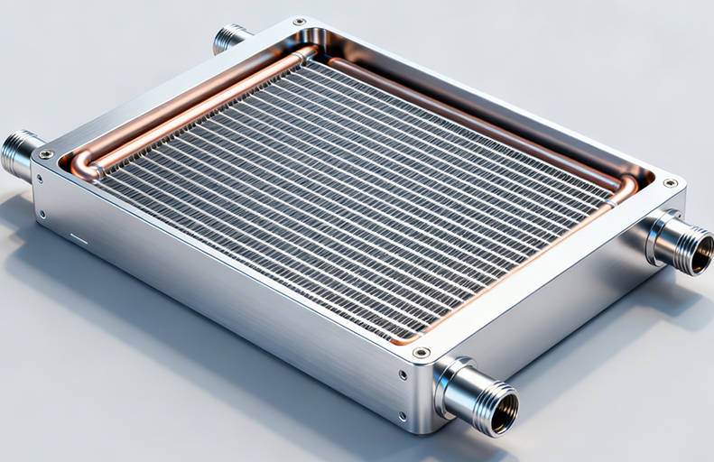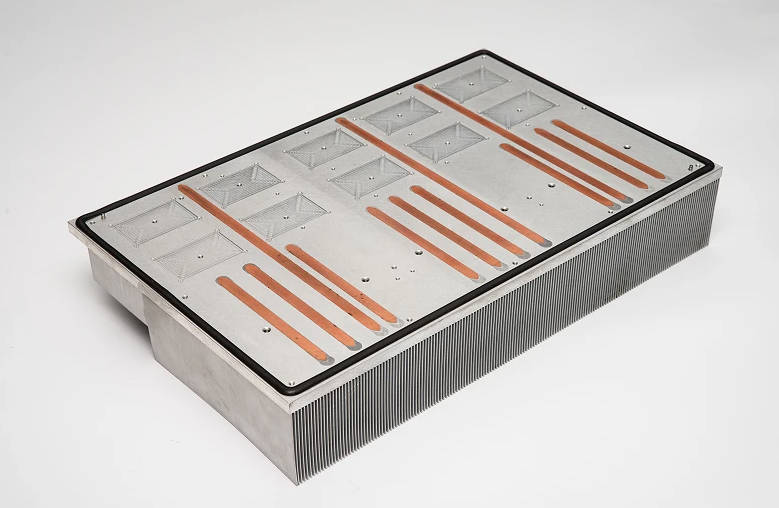
A good liquid cold plate design balances three factors: efficient heat transfer, controlled pressure drop and reliable mechanical sealing. The flow channel must remove heat from the target component, the coolant path must avoid excessive flow resistance, and the cold plate structure must remain leak-resistant under operating pressure.
For high power electronics, EV battery systems, IGBT modules, data centers, laser equipment and industrial devices, air cooling is often not enough. A liquid cold plate transfers heat from a component into a circulating coolant through internal channels. This makes it possible to manage higher heat flux in a compact space.
However, liquid cooling performance does not depend only on the material or the coolant. The real performance comes from the complete liquid cooling plate design: channel layout, contact surface flatness, pressure drop, material selection, manufacturing process, sealing method and testing procedure.
This guide explains the key design factors engineers and buyers should evaluate before choosing or customizing a liquid cold plate.
What Is a Liquid Cold Plate?
A liquid cold plate is a heat exchanger that transfers heat from an electronic component, battery module, power device or mechanical assembly to a liquid coolant. The cold plate usually has a flat mounting surface and internal flow channels. The heat source is attached to the plate, and the coolant flows through the internal passages to carry heat away.
In simple terms, a liquid cold plate replaces part of the heat dissipation burden from air to liquid, allowing higher cooling capacity in a smaller footprint.
Liquid cold plates are commonly used in:
| Application | Typical Heat Source | Why Liquid Cooling Is Used |
| Power electronics | IGBT, MOSFET, inverter, converter | High heat density and continuous operation |
| EV systems | Battery packs, OBC, inverter modules | Compact structure and stable temperature control |
| Data centers | CPUs, GPUs, AI processors | High power density and space limitation |
| Laser equipment | Laser diodes, optical modules | Need stable operating temperature |
| Medical equipment | Imaging or precision control devices | Reliability and temperature stability |
| Telecom equipment | Base stations, power modules | High-load operation in compact enclosures |
A custom cold plate may be made from aluminum, copper or a combination of materials. It may be produced by CNC machining, vacuum brazing, friction stir welding, extrusion, embedded tube structures or other manufacturing processes depending on the required thermal performance, pressure limit, cost target and production volume.
Why Liquid Cold Plate Design Matters
Liquid cold plate design directly affects the safety, reliability and efficiency of the whole cooling system. A plate that looks simple from the outside may contain complex internal channels, manifolds, fins, sealing areas and mounting features.
Poor design can cause:
- Uneven surface temperature
- Local hot spots
- Excessive pressure drop
- Low coolant flow rate
- Pump overload
- Leakage risk
- Corrosion issues
- Poor contact with the heat source
- Higher manufacturing cost
The goal of liquid cold plate design is not only to achieve low thermal resistance, but also to keep the cooling system practical, manufacturable and reliable.
For B2B projects, this is especially important because a cold plate is rarely an isolated part. It is usually integrated into a larger system, such as a battery pack, power module, server rack, laser platform or industrial machine. The design must match the heat source, coolant, flow rate, mounting space and production requirements.
Core Design Principle: Heat Transfer Path
A liquid cold plate removes heat through a chain of thermal transfer steps:
- Heat moves from the component to the thermal interface material.
- Heat passes from the interface material into the cold plate base.
- Heat spreads through the metal plate.
- Heat transfers from the metal surface to the coolant.
- Coolant carries the heat away from the system.
Each step creates thermal resistance. If one step is poorly designed, total cooling performance may decline.
Main Factors Affecting Thermal Performance
| Factor | Impact on Performance | Design Consideration |
| Contact surface flatness | Affects contact resistance | Better flatness improves heat transfer from component to plate |
| Base thickness | Affects heat spreading | Too thick may increase weight; too thin may reduce structural strength |
| Channel position | Affects heat transfer distance | Channels should be close enough to heat sources |
| Channel geometry | Affects turbulence and surface area | More complex channels can improve heat transfer but may increase pressure drop |
| Coolant flow rate | Affects heat removal capacity | Higher flow may improve cooling but increases pump demand |
| Material | Affects conductivity and weight | Copper has high conductivity; aluminum is lightweight and cost-effective |
| Surface treatment | Affects corrosion and durability | Must match coolant chemistry and application environment |
Flow Channel Design in a Liquid Cold Plate
Flow channel design is one of the most important parts of liquid cooling plate design. The channel layout determines how coolant moves inside the plate and how evenly heat is removed from the surface.
A well-designed cold plate flow channel should distribute coolant evenly, avoid dead zones and maintain a reasonable pressure drop.
Common Flow Channel Types
| Flow Channel Type | Advantages | Limitations | Common Applications |
| Straight channel | Simple, low pressure drop, easy to manufacture | May provide less uniform temperature distribution | Extruded plates, standard industrial cooling |
| Serpentine channel | Longer coolant path, improved heat pickup | Higher pressure drop | Power electronics, compact cold plates |
| Parallel channel | Lower pressure drop and better flow distribution when designed well | Risk of flow imbalance if manifolds are poor | Large cold plates, battery cooling |
| Pin fin or micro-fin channel | High heat transfer surface area | More complex and higher pressure drop | High heat flux electronics |
| Embedded tube channel | Coolant path separated inside tube | Less design flexibility than machined channels | Cost-sensitive or corrosion-sensitive projects |
Straight Flow Channels
Straight flow channels are commonly used in extruded liquid cold plates. They are simple and economical, especially for large production volumes. The pressure drop is usually lower than complex channel designs, but thermal performance may be limited if the heat source is concentrated in a small area.
Straight channels are suitable when:
- Heat load is moderate
- The heat source is distributed
- Cost control is important
- Production volume is high
- The design can use a relatively simple coolant path
Serpentine Flow Channels
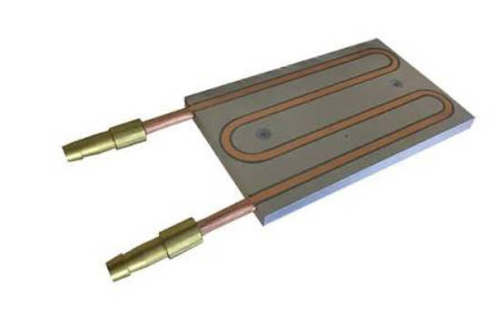
Serpentine channels guide coolant through a longer, winding path. This can improve contact time between coolant and the heated area. It can also help direct coolant through critical hot zones.
However, serpentine channels may create higher pressure drop. The pump must be able to provide enough flow under system resistance.
Serpentine channels are suitable when:
- Heat source area is compact
- Temperature uniformity is important
- Higher cooling performance is needed
- The system can tolerate moderate pressure drop
Parallel Flow Channels
Parallel channels split coolant into multiple paths. This can reduce pressure drop and support larger cooling areas. But the inlet and outlet manifolds must be designed carefully. If one path receives more coolant than another, the plate may develop uneven cooling.
Parallel flow channels are suitable when:
- The cold plate area is large
- Heat sources are spread across the surface
- Flow resistance must be controlled
- Temperature uniformity matters
Understanding Cold Plate Pressure Drop
Pressure drop is the reduction in fluid pressure as coolant flows through the cold plate. It is caused by friction, bends, narrow channels, manifolds, fittings and internal surface features.
Lower pressure drop is not always better, and higher heat transfer is not always better if it creates too much flow resistance. The best design balances both.
If pressure drop is too high, the cooling system may need a larger pump. This increases cost, power consumption, noise and system complexity. If pressure drop is too low because the channels are too large or too simple, heat transfer may not be strong enough for high-power devices.
Factors That Increase Pressure Drop
| Factor | Why It Increases Pressure Drop |
| Narrow channels | Coolant has less space to flow |
| Long flow path | Friction accumulates over distance |
| Sharp bends | Flow separation and turbulence increase resistance |
| High flow rate | Faster coolant movement increases friction |
| Dense fins or internal structures | More surface area but more resistance |
| Poor manifold design | Uneven distribution and local restrictions |
| Small fittings | Connection points may restrict flow |
How to Reduce Pressure Drop in Cold Plate Design
Engineers can reduce cold plate pressure drop by:
- Increasing channel width where possible
- Using smoother bends instead of sharp turns
- Optimizing inlet and outlet manifold geometry
- Reducing unnecessary flow path length
- Balancing parallel channels
- Avoiding oversized internal fin density
- Matching the channel design with pump capability
- Running CFD simulation before prototyping
The design should not focus only on pressure drop reduction. If channels are made too large, coolant may pass through without enough heat transfer. The better approach is to optimize the full relationship between coolant velocity, heat transfer area and flow resistance.
Thermal Performance: What Should Buyers Evaluate?
Thermal performance is usually evaluated by how effectively the cold plate keeps the heat source within the required temperature range. In many projects, engineers look at thermal resistance, temperature rise, coolant flow rate and surface temperature uniformity.
Key Thermal Performance Indicators
| Indicator | Meaning | Why It Matters |
| Thermal resistance | Temperature difference per unit heat load | Lower resistance usually means better heat transfer |
| Surface temperature uniformity | Temperature variation across the mounting surface | Important for batteries, IGBTs and multi-chip modules |
| Coolant temperature rise | Temperature increase from inlet to outlet | Helps evaluate heat removal efficiency |
| Pressure drop | Fluid resistance across the plate | Affects pump selection and system power |
| Maximum operating pressure | Pressure the plate can safely handle | Important for reliability and safety |
| Leak tightness | Ability to prevent coolant leakage | Critical for electronic systems |
For high-power electronics, the design must control both peak temperature and temperature difference across the component. A cold plate that removes heat overall but leaves localized hot spots may still fail in real operation.
Material Selection: Aluminum vs Copper Liquid Cold Plates
Material selection affects thermal performance, weight, corrosion behavior, cost and manufacturing process.
Aluminum Liquid Cold Plates
Aluminum is commonly used because it is lightweight, cost-effective and suitable for many manufacturing processes, including extrusion, CNC machining, brazing and friction stir welding.
Advantages:
- Lower weight than copper
- Good thermal conductivity for many applications
- Cost-effective for larger plates
- Suitable for EV, data center and industrial cooling
- Compatible with several manufacturing methods
Limitations:
- Lower thermal conductivity than copper
- Requires careful corrosion control
- Coolant compatibility must be considered
Copper Liquid Cold Plates
Copper has higher thermal conductivity and is often selected when heat transfer performance is the main priority. It is also common in tube-based designs where copper carries the coolant.
Advantages:
- High thermal conductivity
- Good heat spreading capability
- Suitable for compact high-heat-flux areas
- Useful where copper fluid paths are preferred
Limitations:
- Heavier than aluminum
- Usually higher material cost
- May be less suitable for weight-sensitive systems
Aluminum vs Copper Comparison
| Item | Aluminum Cold Plate | Copper Cold Plate |
| Thermal conductivity | Good | Higher |
| Weight | Lower | Higher |
| Cost | Usually lower | Usually higher |
| Corrosion control | Requires careful coolant and surface treatment selection | Also requires coolant compatibility, but often preferred for tube paths |
| Manufacturing flexibility | High | Good, but cost and weight may limit some designs |
| Common use | EV, data centers, industrial systems, large plates | High heat flux, compact modules, embedded tube designs |
For many B2B projects, aluminum offers a balanced solution. Copper may be used when the heat source is very concentrated, when a copper tube path is preferred, or when the design requires higher thermal conductivity.
Manufacturing Processes for Liquid Cold Plate Design
The manufacturing process determines what channel structure is possible, how much the plate costs, and how reliable the sealing method can be.
Common Liquid Cold Plate Manufacturing Processes
| Process | Best For | Advantages | Considerations |
| CNC machined cold plate | Custom channels and prototypes | Flexible design, precise features | Higher machining cost for complex structures |
| Vacuum brazed cold plate | Complex internal fins and compact designs | High heat transfer surface area | Requires strict process control |
| FSW cold plate | Strong aluminum joints and high-pressure applications | Solid-state joining and good structural integrity | Usually suitable for aluminum structures |
| Extruded cold plate | Cost-sensitive and high-volume projects | Economical and consistent | Channel geometry is less flexible |
| Embedded tube cold plate | Reliable tube-based coolant path | Cost-effective and corrosion-isolated path | Limited channel complexity |
FSW Liquid Cold Plates
Friction stir welding is often used for aluminum cold plates that need strong sealing and structural integrity. A rotating tool joins the cover plate and base material without fully melting the metal. This process is suitable for applications such as EV systems, large inverters and high-pressure liquid cooling structures.
Brazed Liquid Cold Plates
Vacuum brazed cold plates are suitable for complex internal structures. Brazing can join multiple layers and internal fins, which increases the heat transfer surface area. This is useful for compact designs and high heat flux components.
Extruded Liquid Cold Plates
Extruded liquid cold plates use aluminum profiles with channels formed during extrusion. They are suitable for cost-sensitive, repeatable and volume-oriented designs. They are often used when the channel structure can remain relatively simple.
Tube Liquid Cold Plates
Tube liquid cold plates use copper or stainless steel tubes embedded into a metal base. The coolant flows inside the tube, while the base plate spreads heat from the component. This design can reduce direct coolant contact with aluminum and may be attractive for specific corrosion or cost requirements.
For projects that require a customized thermal path, pressure target and mounting interface, working with a custom liquid cold plate manufacturer can help align design, manufacturability and testing from the early stage.
Design Trade-Offs: Performance, Pressure Drop and Cost
Liquid cold plate design is always a trade-off. A design that maximizes heat transfer may not be the most cost-effective or easiest to manufacture. A design that minimizes pressure drop may not provide enough cooling in high heat flux areas.
Common Design Trade-Offs
| Design Goal | Possible Benefit | Possible Risk |
| Increase channel density | Better heat transfer surface area | Higher pressure drop and manufacturing complexity |
| Use thinner base | Lower thermal resistance | Lower structural strength or flatness stability |
| Increase coolant flow rate | Better heat removal | Higher pump power and pressure drop |
| Use copper | Better conductivity | Higher weight and cost |
| Use complex internal fins | Stronger heat transfer | Higher pressure drop and process complexity |
| Use extrusion | Lower cost for volume production | Less channel design flexibility |
| Use brazing | Complex internal structures | Requires careful process and cleanliness control |
A practical liquid cooling plate design must match the real operating conditions. These include heat load, coolant type, inlet temperature, flow rate, allowable pressure drop, space constraints, mounting requirements, service life and production volume.
How to Design a Liquid Cold Plate: Engineering Workflow
A typical cold plate design process includes the following steps.
Step 1: Define Thermal Requirements
The first step is to understand the heat source. Engineers should define:
- Heat load in watts
- Heat source size and location
- Maximum allowable component temperature
- Ambient or coolant inlet temperature
- Required temperature uniformity
- Operating duty cycle
Without this information, the design may be based on assumptions rather than actual application needs.
Step 2: Select Material and Manufacturing Process
The material and manufacturing process should be selected according to performance, size, cost and pressure requirements. For example, a high-volume industrial cooling project may use extruded aluminum, while a compact high-heat-flux module may require a brazed or CNC-machined structure.
Step 3: Design the Flow Channel
The flow channel should place coolant close to critical heat zones while keeping pressure drop within the system limit. Engineers may compare straight, serpentine, parallel and fin-enhanced channels.
Step 4: Evaluate Pressure Drop
Pressure drop should be evaluated early because it affects pump selection. The design should not be finalized before checking whether the pump can provide the required flow rate.
Step 5: Run Thermal and Flow Simulation
CFD and thermal simulation can help identify hot spots, flow imbalance and dead zones before prototyping. This reduces trial-and-error and helps improve the first sample design.
Step 6: Prototype and Test
Prototype testing should verify:
- Leak tightness
- Flow resistance
- Pressure capability
- Thermal performance
- Surface flatness
- Mounting compatibility
- Cleanliness of internal channels
A design is not complete until it is tested under conditions close to the actual application.
Common Mistakes in Liquid Cooling Plate Design
Mistake 1: Focusing Only on Thermal Conductivity
Material conductivity is important, but it is not the whole design. A copper plate with poor channel layout may perform worse than an optimized aluminum design.
Mistake 2: Ignoring Pressure Drop
Some designs improve heat transfer by using narrow or complex channels, but the pump may not be able to maintain enough flow. This can reduce real system performance.
Mistake 3: Poor Flow Distribution
In large parallel-channel designs, coolant may not flow evenly through every path. This can create hot areas even when total flow rate looks sufficient.
Mistake 4: Underestimating Surface Flatness
If the cold plate surface is not flat enough, the thermal interface may not contact the heat source evenly. This increases contact resistance.
Mistake 5: Choosing a Manufacturing Process Too Late
Some channel designs are not suitable for every process. The manufacturing method should be considered during design, not after the design is finished.
Mistake 6: Not Considering Coolant Compatibility
Coolant chemistry, metal selection and surface treatment must work together. Corrosion can become a long-term reliability issue if it is ignored.
How to Choose the Right Liquid Cold Plate Supplier
For B2B projects, choosing the right supplier is not only about price. The supplier should understand thermal design, manufacturability, pressure testing and quality control.
Key Supplier Evaluation Points
| Evaluation Point | Why It Matters |
| Thermal design support | Helps optimize channel layout, flow rate and heat transfer |
| Manufacturing process options | Allows better matching between performance and cost |
| CFD or simulation capability | Reduces design risk before prototyping |
| Pressure and leak testing | Critical for liquid cooling reliability |
| CNC and surface finishing capability | Affects flatness, tolerance and assembly quality |
| Experience with target applications | Helps avoid design mistakes in EV, power electronics, data centers or lasers |
| Prototype-to-production support | Makes scaling easier after validation |
When discussing a project with Jindu Tech, engineers can provide drawings, heat source data, coolant conditions, flow requirements and installation constraints so the team can evaluate a suitable liquid cooling plate design.
What Information Should You Provide for a Custom Liquid Cold Plate Quote?
To speed up evaluation and avoid unclear assumptions, prepare the following information before requesting a custom design.
| Information | Example |
| Heat load | Total watts and heat source distribution |
| Component size | Contact area and mounting location |
| Maximum temperature | Allowable surface or component temperature |
| Coolant type | Water-glycol, deionized water or other coolant |
| Flow rate | Target or available flow rate |
| Pressure drop limit | Maximum acceptable pressure loss |
| Operating pressure | Normal and maximum pressure |
| Material preference | Aluminum, copper or hybrid |
| Size limit | Length, width, thickness and mounting space |
| Interface requirements | Fittings, ports, seals, surface treatment |
| Production volume | Prototype, small batch or mass production |
| Testing requirements | Leak test, pressure test, thermal test, cleanliness |
Providing this information helps the supplier recommend whether FSW, brazing, extrusion, CNC machining or embedded tube design is more suitable.
FAQ
What is the most important factor in liquid cold plate design?
The most important factor is balance. A good liquid cold plate design must balance thermal performance, pressure drop, manufacturability and sealing reliability. Channel layout, material, coolant flow and surface flatness all affect final performance.
How does cold plate flow channel design affect thermal performance?
Cold plate flow channel design affects how coolant reaches the heat source and how evenly heat is removed. A good channel layout reduces hot spots, improves temperature uniformity and keeps flow resistance within an acceptable range.
How can I reduce pressure drop in a liquid cold plate?
Pressure drop can be reduced by optimizing channel width, shortening unnecessary flow paths, using smoother bends, improving manifold design and balancing parallel channels. However, the design must still maintain enough coolant velocity and heat transfer surface area.
Is aluminum or copper better for a liquid cold plate?
Copper has higher thermal conductivity, while aluminum is lighter and usually more cost-effective. Aluminum is commonly used for larger plates and volume production, while copper may be preferred for compact high-heat-flux areas or tube-based coolant paths.
What is a typical application for a custom liquid cold plate?
Custom liquid cold plates are commonly used in power electronics, EV battery systems, inverters, IGBT modules, AI servers, GPU cooling, laser equipment, medical devices and industrial machines where air cooling cannot meet the thermal requirement.
What is the difference between FSW and brazed liquid cold plates?
FSW liquid cold plates are often used for aluminum structures requiring strong joints and pressure resistance. Brazed liquid cold plates are suitable for complex internal channels and fin structures where high heat transfer area is needed.
Why is pressure drop important in liquid cooling plate design?
Pressure drop affects pump selection, coolant flow rate and total system efficiency. If pressure drop is too high, the pump may not deliver enough flow, which can reduce real cooling performance even if the cold plate looks effective in theory.
What should I send to a liquid cold plate manufacturer for design evaluation?
You should provide heat load, heat source size, target temperature, coolant type, flow rate, pressure limit, material preference, size restrictions, mounting details, production volume and testing requirements.
Conclusion
Liquid cold plate design is a system-level engineering task. Flow channel layout, pressure drop, material choice, manufacturing process, surface flatness and leak testing all affect the final cooling result.
The most effective liquid cooling plate is not simply the one with the most complex channels or the highest conductivity material. It is the design that meets the thermal target while staying reliable, manufacturable and compatible with the whole cooling system.
For high power electronics, EV systems, AI servers, GPU modules, laser equipment and industrial devices, a custom cold plate can provide the thermal performance needed for compact and high-load operation.
Jindu Tech provides custom liquid cold plate solutions for projects that require optimized flow channels, controlled pressure drop and reliable manufacturing. If you are developing a new liquid cooling system, send your drawings and thermal requirements for engineering review.