A heat sink transfers heat away from a component and releases it into the surrounding air or another cooling medium. Most conventional designs use a conductive base and extended fins to increase the area available for heat dissipation. But material and size alone do not determine performance. Fin spacing, airflow, thermal interface material (TIM), and mounting conditions all affect how much heat a heat sink can remove. For engineers and technical buyers, the key is to evaluate the complete thermal path, from the heat-generating component to the surrounding environment. This guide explains how heat sinks work, which design variables matter, how to choose a cooling approach, and how to interpret datasheet specifications.

What Is a Heat Sink?
The Core Definition: A Heat Exchanger, Not Just a Piece of Metal
A heat sink is a heat exchanger that transfers thermal energy from a heat-generating component to a surrounding medium, usually air. Its purpose is to keep the component within its specified operating temperature range.
Heat sinks are commonly used with processors, power transistors, LED modules, voltage regulators, and other electronic components that generate heat during operation.
Consider a power transistor inside an industrial control cabinet. As electrical current passes through it, some energy becomes heat. If that heat cannot escape, the junction temperature rises. Prolonged exposure to excessive temperatures can accelerate component aging, cause thermal shutdown, or lead to premature failure.
A heat sink provides a path for that energy to escape. It receives heat through contact with the component, spreads it through a conductive structure, and transfers it to the surrounding air through convection.
Some designs rely on natural airflow. Others use fans to move air across the fins. The underlying function is the same: move heat away from the source and release it into the environment.
A heat sink is therefore more than a metal block. Its performance depends on how effectively its structure conducts, spreads, and releases heat under actual operating conditions.
What a Heat Sink Is Not: Heat Spreader, Cold Plate, and Vapor Chamber Are Not the Same Thing
Heat sinks, heat spreaders, cold plates, and vapor chambers all play a role in thermal management, but they solve different problems. The distinction matters when deciding which components a cooling system actually needs.
Heat sink: A heat sink removes heat from a component and transfers it to the surrounding environment. Its base receives heat, while its fins provide additional surface area for convection. Most conventional heat sinks use air as the cooling medium.
Heat spreader: A heat spreader distributes concentrated heat across a larger surface. It helps reduce hot spots, but does not necessarily provide enough surface area to release that heat into the environment. A flat copper plate, for example, can spread heat across an electronic package without replacing the need for a finned heat sink.
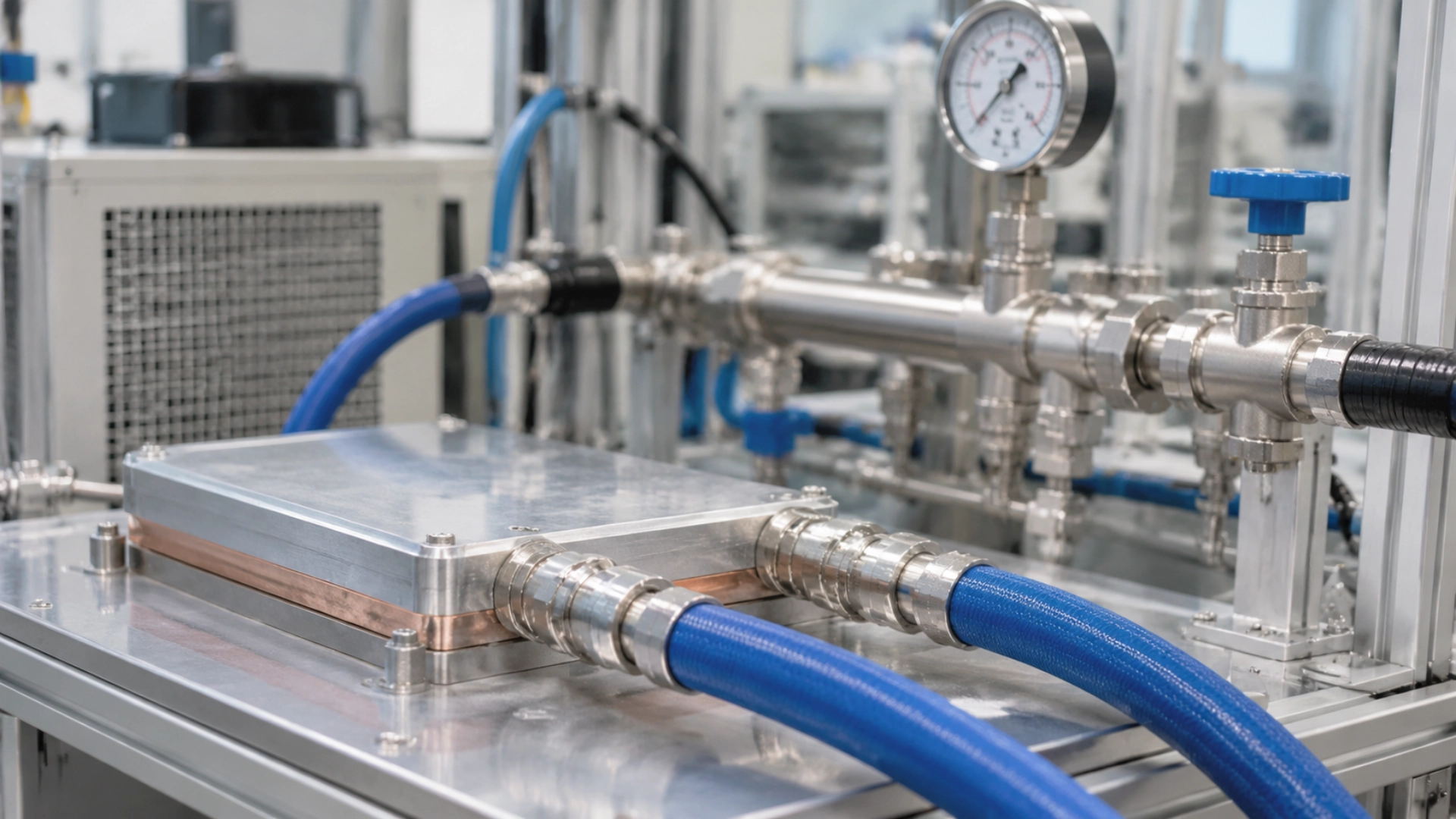
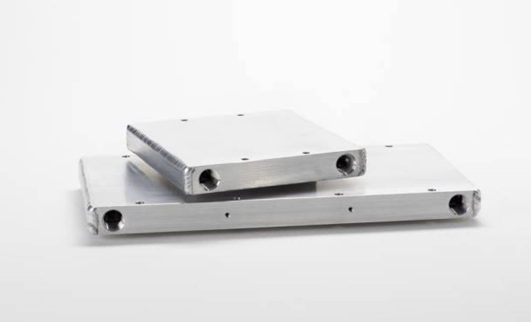
Cold plate: A cold plate transfers heat to circulating liquid through internal channels or passages. The coolant carries the heat to another part of the system, such as a radiator or heat exchanger. Cold plates are common in EV battery systems, data centers, and high-power electronics.
Vapor chamber: A vapor chamber uses a sealed internal chamber and a working fluid to spread heat through evaporation and condensation. Heat absorbed near the source causes the fluid to evaporate. The vapor moves toward cooler regions, condenses, and releases heat. A wick structure returns the liquid to the heated area.
| Component | Main Function | Heat Transfer Method | Typical Applications |
|---|---|---|---|
| Heat sink | Remove heat and release it into the environment | Conduction and convection | Processors, power electronics, LED systems |
| Heat spreader | Distribute concentrated heat | Conduction | Electronic packages, semiconductor modules |
| Cold plate | Transfer heat to circulating coolant | Conduction and liquid convection | EV batteries, data centers, power electronics |
| Vapor chamber | Spread heat across a larger area | Phase change and internal vapor transport | Compact electronics, high-density processors |
These technologies can also work together. A vapor chamber, for example, can spread heat from a small processor across a larger finned structure. A cold plate may replace an air-cooled heat sink when the heat load exceeds what the available airflow can handle.
The Three Elements Every Heat Sink Shares: Base, Fins, and Thermal Interface
Most conventional heat sinks have three essential elements: a base, a fin structure, and a thermal interface. Each has a different role in the heat transfer process.
1. Base
The base receives heat from the component and distributes it toward the fins. It usually contacts the heat source through a thermal interface material.
Base thickness and flatness affect how heat spreads. A base that is too thin may struggle to distribute heat from a small, high-power semiconductor across the full fin structure. Increasing thickness can help, but it also adds weight and material cost. More metal does not automatically produce a lower operating temperature.
2. Fins
Fins increase the surface area exposed to the surrounding air. This gives heat more area through which to leave the heat sink.
Their height, thickness, spacing, and orientation all affect performance. Closely spaced fins provide more surface area, but they can also restrict airflow. If air cannot pass through the channels, much of the additional surface area may contribute little to cooling.
3. Thermal Interface
The thermal interface connects the component to the heat sink. Common materials include thermal grease, thermal pads, and phase-change materials.
Even machined metal surfaces have microscopic irregularities. When two surfaces are pressed together, small air gaps remain between them. Because air conducts heat poorly, these gaps increase thermal resistance.
A suitable TIM fills the gaps and improves heat transfer. Its thickness, conductivity, compression, and installation quality all matter.
How Does a Heat Sink Work? The Four-Step Thermal Path
Heat moves through a heat sink in four stages: it is generated at the component, passes into the base, spreads through the fins, and transfers into the surrounding air.
The cooling system is only as effective as its complete thermal path. A highly conductive base cannot compensate for poor contact with the component, and a large fin area cannot deliver good results if airflow is restricted.
Step 1: Heat Generation and Spreading at the Source
The process starts inside the component. Electrical resistance, switching losses, and semiconductor operation convert part of the input energy into heat.
A processor may generate heat across several active regions of its silicon die. A power transistor may concentrate heat in a relatively small semiconductor junction. An LED module produces heat because only part of its electrical input becomes visible light.
These differences affect heat sink design. Total power dissipation is important, but so is the area over which that heat enters the cooling system.
For example, two components may each dissipate 50 W. One distributes heat across a large contact surface, while the other concentrates it in a small area. The second application may require better heat spreading at the base to avoid localized hot spots.
Before selecting a heat sink, establish four basic conditions:
- Actual heat load: How many watts does the component dissipate under the intended operating conditions?
- Heat source area: Is heat distributed across a large surface or concentrated in a small region?
- Temperature limit: What is the maximum allowable junction, case, or operating temperature?
- Operating pattern: Is the heat load continuous, intermittent, or variable?
These values define the thermal conditions the cooling system must handle.
Step 2: Conduction Through the Base and the Thermal Interface
Heat enters the heat sink through conduction. The thermal interface sits between the component and the base, filling microscopic gaps that would otherwise restrict heat transfer.
Once heat passes through the interface, it moves into the base and spreads across the structure.
Material conductivity affects this process. Copper generally conducts heat better than aluminum, making it useful when heat enters through a small contact area or needs to spread quickly across the base.
But conductivity is only part of the picture. A copper heat sink can still perform poorly if the mounting surface is uneven or the thermal pad is unnecessarily thick.
Imagine a power module mounted to a copper base with an oversized thermal pad. The copper may spread heat efficiently, but the thick interface adds resistance before heat even reaches the base.
For this reason, engineers should evaluate the material, contact area, TIM thickness, and mounting arrangement together.
Step 3: Diffusion Across the Fin Structure
After entering the base, heat spreads into the fins. These extended surfaces provide the area needed to transfer heat into the surrounding air.
However, fin temperature is not uniform. Heat moves from the base toward the fin tips while continuously escaping into the air. As a result, the temperature generally decreases along the fin length.
This explains why making fins taller does not always improve cooling in proportion to the added surface area. If the fin is too long or the material does not conduct heat efficiently enough, its outer sections may remain much cooler than the base and contribute less to heat dissipation.
Fin efficiency describes how effectively a fin uses its available surface area compared with an ideal fin maintained at the base temperature.
Engineers should therefore consider fin height, thickness, material conductivity, and airflow as a connected set of design variables. Additional surface area is useful only when heat can reach it and the surrounding medium can carry that heat away.
Step 4: Convection into the Ambient Medium
The final stage is convection: heat transfers from the fin surfaces into the surrounding air or another fluid.
When air passes over a warm fin, it absorbs thermal energy and carries it away. Cooler air then replaces the heated air, allowing the process to continue.
There are two common ways to move air across a heat sink.
Natural convection relies on temperature differences. Warm air becomes less dense and rises, while cooler air moves in to replace it. No fan is needed, but airflow is usually limited.
Forced convection uses a fan or blower to move air across the fins. Higher airflow can improve heat transfer and support greater heat loads within the same installation space.
However, fan speed alone does not determine cooling performance. The fan must overcome the resistance of the fin channels, enclosure, filters, and other components in the airflow path.
Ambient temperature also matters. If the surrounding air is already hot, the temperature difference between the fins and air becomes smaller. The heat sink then has less capacity to reject heat at the same operating temperature.
Where the Bottleneck Usually Is: The TIM Interface and the Air-Side Boundary Layer
Two parts of the thermal path often limit heat sink performance: the interface between the component and base, and the boundary layer of air around the fins.
The TIM interface
A thermal interface becomes a problem when it is too thick, poorly applied, or installed under insufficient pressure. These conditions increase contact resistance and prevent heat from entering the heat sink efficiently.
For example, a thick thermal pad may be necessary to accommodate a mechanical gap, but it usually adds more resistance than a properly fitted thin interface. Uneven mounting pressure can create the same problem by leaving parts of the contact surface poorly connected.
The air-side boundary layer
As air flows over a fin, a thin layer of relatively slow-moving air forms near the surface. This is the thermal boundary layer. Heat must pass through it before entering the main airflow.
Weak airflow can make this layer less effective at carrying heat away. Increasing airflow velocity generally improves convection, although it also increases pressure drop and may require a more powerful fan.
The practical lesson is simple: improving the base material or adding fins will not solve every thermal problem. Engineers must identify where resistance is concentrated before changing the design.
The Design Variables That Actually Determine Performance
Four factors have a direct influence on heat sink performance: fin geometry, material, thermal interface, and airflow. They interact. Changing one can affect the others, so each should be evaluated under the same operating conditions.
Fin Geometry: Surface Area vs. Airflow Resistance
Fin geometry involves a trade-off between available surface area and airflow resistance. More fins can increase the area available for heat transfer, but they also reduce the space through which air must pass.
Consider a heat sink installed in a compact power supply. A dense fin arrangement may look attractive because it provides a large surface area. But if the fan cannot push enough air through the narrow channels, the actual cooling performance may fall short.
Several dimensions influence this balance:
- Fin height: Taller fins increase surface area, but heat may not reach their tips efficiently.
- Fin thickness: Thicker fins can improve structural strength and heat conduction, but add weight and reduce airflow space.
- Fin spacing: Narrow spacing increases fin density but can raise pressure drop and restrict airflow.
- Fin orientation: The direction of the fins affects how air moves through the structure, especially under natural convection.
- Base thickness: A thicker base can improve heat spreading under concentrated heat loads, but increases material use and weight.
Natural-convection designs generally need open passages that allow warm air to rise. Forced-air designs can use denser fins, provided the fan has enough pressure capability to maintain the required airflow.
There is no single fin geometry that works best in every application. The design must match the heat load, available space, cooling method, and airflow conditions.
Material Choice: Aluminum vs. Copper vs. Hybrid — The Real Trade-Offs
Aluminum, copper, and hybrid constructions are common heat sink options. The right choice depends on how much heat must be spread, how much weight the assembly can support, and what the manufacturing budget allows.
Aluminum
Aluminum is widely used because it combines relatively low weight, good thermal conductivity, and cost-effective manufacturing.
It is particularly suitable for extruded heat sinks used in industrial control equipment, LED lighting, power supplies, and general electronic assemblies. Extrusion allows manufacturers to produce long fin profiles efficiently.
Its main limitation is lower thermal conductivity than copper. When a small semiconductor produces concentrated heat, aluminum may spread that heat less effectively across the base.
Copper
Copper has higher thermal conductivity than aluminum. It is useful when heat must spread quickly from a concentrated source or when reducing temperature differences across the base is important.
The trade-offs are weight and cost. Copper is significantly denser than aluminum and is generally more expensive. A fully copper heat sink may therefore be unsuitable for assemblies with strict weight limits or tight manufacturing budgets.
Hybrid construction
Hybrid heat sinks combine copper and aluminum in one structure. A common arrangement uses a copper base or insert to receive heat from the component, with aluminum fins providing a larger surface area for convection.
This can reduce the weight and material cost of an all-copper design while improving heat spreading near the source compared with an all-aluminum structure.
The connection between the two materials needs attention. The joint must maintain good thermal contact and mechanical stability. Differences in thermal expansion can also affect reliability during repeated heating and cooling cycles.
| Evaluation Factor | Aluminum | Copper | Hybrid |
|---|---|---|---|
| Thermal conductivity | Moderate to high | High | Depends on material arrangement |
| Weight | Low | High | Depends on copper content |
| Material cost | Generally lower | Generally higher | Depends on construction |
| Heat spreading | Suitable for many general applications | Strong heat spreading capability | Can improve spreading near concentrated heat sources |
| Manufacturing | Well suited to extrusion | Suitable for machining and skiving | Requires reliable material joining or integration |
| Main consideration | Weight and cost efficiency | Conductivity and weight | Balancing performance, weight, and cost |
Higher conductivity does not automatically mean lower system temperature. If the thermal interface is poor or airflow is insufficient, the benefit of copper may be limited.
Choose materials based on the actual bottleneck. Copper is worth considering when heat spreading is a limiting factor. Aluminum is often sufficient when weight, cost, and manufacturing efficiency matter more. Hybrid construction is an option when the design needs both.
TIM and Mounting Pressure: The Interface Nobody Talks About
The thermal interface can make or break the connection between a component and its heat sink. Even a well-designed fin structure cannot perform properly if heat struggles to enter the base.
Common TIM options include thermal grease, thermal pads, and phase-change materials. They differ in thickness, conductivity, compression behavior, and installation requirements.
- Thermal grease: Forms a thin interface layer and can provide low thermal resistance when applied correctly. Application consistency and long-term stability need consideration.
- Thermal pads: Are easier to handle and can accommodate gaps between surfaces. However, thicker pads generally introduce more thermal resistance than thinner interfaces made from comparable materials.
- Phase-change materials: Soften or change their physical behavior at operating temperatures, helping them conform to surface irregularities.
Do not compare TIM products using thermal conductivity alone. Thickness, electrical insulation, operating temperature range, compression, and long-term reliability also affect the result.
Mounting pressure matters just as much. Insufficient pressure can leave air gaps between surfaces. Excessive pressure may damage the component, deform the base, or push interface material away from the contact area.
Before evaluating a heat sink assembly, check:
- Contact surface flatness and roughness.
- TIM type and specified thickness.
- Required mounting torque or clamping force.
- Contact area between the component and base.
- Mechanical stability under vibration and thermal cycling.
Published thermal resistance values are meaningful only when the test interface and mounting conditions are understood. If the final assembly uses a different TIM or mounting arrangement, actual performance may differ.
Airflow Regime: Natural Convection vs. Forced Convection vs. Liquid Cooling
The cooling medium determines how heat leaves the heat sink. Natural convection uses temperature-driven air movement, forced convection uses a fan or blower, and liquid cooling transfers heat through circulating coolant.
Natural convection
Natural convection works without a fan. Warm air rises from the fin surfaces, and cooler air moves in to replace it.
This approach is useful when noise, power consumption, and maintenance are priorities. It is commonly considered for low-to-moderate heat loads in industrial electronics, passive power supplies, and LED assemblies.
Its limitation is airflow capacity. Restricted enclosures, poor fin orientation, and high ambient temperatures can reduce cooling performance.
Forced convection
Forced convection uses a fan or blower to move air through the fin channels. It can remove more heat from a given surface area than natural convection when airflow is properly matched to the design.
However, the fan must overcome the pressure drop created by the heat sink and the rest of the enclosure. A fan’s maximum free-airflow rating is not the airflow it will necessarily deliver after installation.
Engineers should compare the fan curve with the system resistance curve and evaluate the resulting operating point.
Liquid cooling
Liquid cooling uses circulating coolant to transport heat away from the component. A cold plate transfers heat into the fluid, which carries it to a radiator or another heat exchanger.
This approach is used in high-power electronics, EV battery systems, and data centers where air cooling cannot meet the required heat removal capacity within the available space.
Liquid cooling also introduces pumps, coolant passages, seals, and fluid management requirements. The complete system must be evaluated, not just the cold plate.
The choice depends on heat load, installation volume, allowable temperature rise, maintenance requirements, and system complexity.
Passive, Active, and Hybrid: Choosing the Cooling Mode for Your Constraints
The choice between passive, active, and hybrid cooling depends on what the system can accommodate. A passive design avoids fans and moving parts. An active design uses forced airflow to handle higher heat loads. A hybrid design combines both and adjusts cooling according to operating conditions.
Passive: When Silence and Reliability Outweigh Peak Performance
A passive heat sink relies on natural convection and thermal radiation. It has no fan, motor, or other powered airflow device.
This makes it suitable for equipment where noise, maintenance, and moving-part reliability are major concerns. Examples include industrial control cabinets, LED lighting assemblies, and electronic equipment operating in environments where fan replacement is inconvenient.
The trade-off is cooling capacity. Without forced airflow, the design needs enough exposed surface area and sufficient space for warm air to escape.
Fin orientation matters. If a vertically oriented passive heat sink is installed horizontally in a tightly enclosed space, natural airflow may become less effective.
Passive cooling is worth considering when:
- The heat load can be handled by natural convection.
- Fan noise is unacceptable.
- The system requires minimal maintenance.
- There is enough space for a suitable fin structure.
- The enclosure allows warm air to escape.
If these conditions cannot be met, forced airflow or another cooling method may be necessary.
Active: When Airflow Is Available and Heat Load Is High
An active heat sink uses a fan or blower to force air across its fins. This increases convection and allows the system to handle higher heat loads without relying entirely on a large passive structure.
Processors, power converters, and compact industrial electronics commonly use forced-air cooling when natural convection cannot maintain the required operating temperature.
However, the fan and heat sink must be designed as a pair.
Fan performance: The fan needs sufficient pressure to push air through the fin channels. Its free-airflow rating alone is not enough to predict installed performance.
Airflow distribution: Air should pass through the intended fin area. If it bypasses the fins or encounters obstructions, cooling becomes less effective.
Noise and power: Increasing fan speed can improve heat transfer, but also raises acoustic output and electrical consumption.
Reliability: Fans have moving parts. Dust, bearing wear, and motor failure can affect long-term operation.
Active cooling is appropriate when the required heat removal exceeds natural convection capacity and the system can accommodate fan power, noise, and maintenance.
Hybrid: The Control Logic That Combines Both
Hybrid cooling combines a passive heat sink with controlled airflow or another cooling mechanism. A common arrangement uses a fan that starts only when the component temperature reaches a specified threshold.
For example, an industrial electronic controller may operate without fan assistance under a light load. When its power transistors heat up during a high-load cycle, the control system increases fan speed to maintain the required temperature.
Common control methods include:
- Temperature-based control: Fan operation responds to a measured component or heat sink temperature.
- Variable-speed control: Fan speed increases or decreases according to thermal demand.
- Load-based control: Airflow is adjusted using estimated power consumption or operating conditions.
- Hysteresis control: Separate activation and deactivation thresholds prevent frequent fan cycling.
Hybrid cooling can reduce average fan operation while retaining additional cooling capacity when the thermal load rises.
However, it requires reliable sensors, control logic, and fan operation. Engineers should also determine how the system responds if the fan fails or the heat load exceeds the expected range.
Liquid Cooling and Vapor Chambers: When a Heat Sink Alone Is Not Enough
Some thermal problems cannot be solved by changing the fin geometry or using a more conductive metal. When heat flux is too high, installation space is limited, or airflow cannot provide enough cooling, engineers may need liquid cooling or additional heat spreading technology.
Liquid cooling
A liquid cooling system uses a cold plate to transfer heat into circulating coolant. Internal channels guide the fluid across the heated region. The coolant then carries the energy to a radiator or another heat exchanger.
This is useful in high-power data center equipment, EV battery thermal management, and power electronic assemblies where substantial heat must be removed from a relatively small area.
The additional hardware matters. Pumps, seals, coolant compatibility, pressure management, and leak prevention all become part of the thermal design.
Vapor chambers
A vapor chamber spreads heat across a larger surface through evaporation and condensation.
When one region is heated, the internal working fluid evaporates. Vapor moves toward cooler regions, condenses, and releases heat. A wick returns the liquid to the heated area through capillary action.
This helps distribute concentrated heat across a larger area before it reaches the external cooling structure.
Vapor chambers are useful in compact electronics where a small heat source needs to transfer energy to a wider fin structure. They do not eliminate the need for heat rejection. The heat must still leave the vapor chamber through a heat sink or another cooling system.
The difference is important: a cold plate transports heat through circulating liquid, while a vapor chamber primarily improves heat spreading within a sealed structure.
Common Evaluation Mistakes Engineers Make
Heat sink specifications can look suitable on paper but produce disappointing results after installation. The problem often comes from evaluating one parameter without considering the full cooling system.
Sizing by TDP Alone Without Accounting for Actual Airflow
TDP is a useful starting point, but it should not be treated as the only value needed to select a heat sink.
Depending on the component and manufacturer, TDP may represent a design-related thermal power specification rather than the maximum heat generated under every operating condition. Actual power dissipation can change with workload, voltage, switching frequency, and system configuration.
Airflow introduces another variable.
Consider two identical heat sinks installed in different enclosures. One receives direct airflow from a fan. The other sits behind a cable bundle with limited ventilation. Even with the same heat load, their operating temperatures can differ because the airflow conditions are different.
Engineers should check:
- Actual power dissipation under the intended workload.
- Maximum ambient temperature.
- Available airflow rate and direction.
- Enclosure ventilation and nearby obstructions.
- Fan performance under installed system resistance.
- Required temperature margin.
Size the heat sink against the actual operating conditions, not TDP alone.
Ignoring TIM and Mounting Pressure in the Thermal Path
A heat sink’s published thermal resistance does not always represent the resistance of the complete component-to-air path.
The thermal interface adds resistance between the component and the heat sink. Its contribution depends on material type, thickness, contact area, and mounting pressure.
For example, a laboratory test may use a thin layer of thermal grease under controlled mounting pressure. The final product may use a thicker thermal pad to accommodate a mechanical gap. The installed assembly can therefore have higher thermal resistance than the published test result suggests.
Uneven mounting pressure can make the problem worse. Some areas may have good contact while others remain separated by air gaps.
When evaluating a heat sink, confirm the TIM specification and mounting conditions. Also check whether the published thermal resistance includes the component interface or describes only the heat sink-to-air section.
Confusing Heat Spreader Performance with Heat Sink Performance
A heat spreader distributes heat. A heat sink releases it into the surrounding environment. These are different functions.
A copper plate may spread heat across a larger area, reducing a localized hot spot. But unless it has sufficient surface area and an effective path for heat rejection, it may not keep a high-power component within its operating temperature limit.
The same distinction applies to vapor chambers. Their ability to spread heat does not mean they can independently remove all the heat generated by a component.
When reviewing a thermal design, identify what each component actually does. Then check whether the complete assembly has enough capacity to transfer heat into the environment.
Assuming a Bigger Heat Sink Is Always Better
A larger heat sink can provide more surface area, but its physical size does not guarantee better cooling.
Increasing fin density may raise pressure drop. If the fan cannot maintain sufficient airflow, the additional surface area may not deliver the expected improvement.
Taller fins also have limits. Heat must travel from the base toward the fin tips, and the outer sections may contribute less when fin efficiency is low.
There are mechanical and practical constraints as well:
- Weight: A larger structure adds load to circuit boards and mounting brackets.
- Installation space: The heat sink may interfere with nearby components or block airflow.
- Cost: More material and additional manufacturing operations increase production costs.
- Airflow: A larger or denser structure may require a different fan or duct arrangement.
The goal is not to maximize heat sink size. It is to achieve the required thermal performance within the available space, airflow, weight, and cost limits.
How to Read a Heat Sink Datasheet
A heat sink datasheet helps engineers compare designs, estimate temperature rise, and check whether a cooling structure matches the intended application.
Three areas deserve particular attention: thermal resistance, pressure drop, and the test conditions behind the published values. A specification is only useful when its measurement conditions are understood.
Thermal Resistance (θ) and What It Actually Tells You — and What It Does Not
Thermal resistance describes the temperature difference required to transfer a given amount of heat through a thermal path. It is usually expressed in °C/W or K/W.
For a simplified steady-state system, the relationship is:
ΔT = Q × Rθ
Where:
- ΔT: Temperature difference across the thermal path, in °C or K.
- Q: Heat dissipation rate, in watts (W).
- Rθ: Thermal resistance, in °C/W or K/W.
For example, if a heat sink has a thermal resistance of 2.0°C/W under a specified test condition and dissipates 20 W, the estimated temperature rise from the defined reference point to ambient is:
ΔT = 20 W × 2.0°C/W = 40°C
If the ambient temperature is 30°C, the estimated reference temperature is 70°C under those same test conditions.
This calculation is useful for a first estimate, but it does not mean every heat sink with a rating of 2.0°C/W will produce the same result in an actual assembly.
Thermal resistance depends on airflow, orientation, heat source dimensions, mounting conditions, and test setup. Engineers must also identify which section of the thermal path the specification describes.
Common thermal resistance values include:
- θSA: Heat sink-to-ambient thermal resistance.
- θCS: Component case-to-heat sink thermal resistance.
- θJC: Component junction-to-case thermal resistance.
- θJA: Component junction-to-ambient thermal resistance under a defined test configuration.
For a simplified series thermal path, the total resistance can be estimated as:
θJA ≈ θJC + θCS + θSA
This approximation assumes a predominantly series heat flow path. Actual assemblies may include additional heat paths, spreading resistance, and complex thermal interactions.
When comparing datasheets, check:
- Airflow velocity and fan configuration.
- Heat input and source dimensions.
- Heat sink orientation.
- Ambient temperature and test environment.
- Whether TIM and mounting resistance are included.
A lower thermal resistance generally indicates better heat transfer when the test conditions are comparable. Without comparable conditions, the numbers can be misleading.
Pressure Drop and Airflow Curves: Why the Fan Curve Matters as Much as the Fin Area
In forced-air cooling, the fan and heat sink must work together. The heat sink creates resistance as air passes through its fin channels, while the fan supplies the pressure needed to move that air.
Pressure drop is the difference in air pressure between the inlet and outlet of the heat sink. It is commonly measured in pascals (Pa).
Fin spacing, thickness, channel length, and geometry all affect pressure drop. Narrow channels may increase surface area, but they also make it harder for air to pass through.
This is where the fan curve becomes important.
A fan performance curve shows the relationship between airflow rate and static pressure. As system resistance increases, the airflow delivered by the fan generally decreases.
The actual operating point is where the fan curve intersects the system resistance curve. This point determines the airflow the fan can deliver in the installed system.
For example, a fan rated at a high free-airflow value may deliver much less air when connected to a dense heat sink inside a restricted enclosure. Using the free-airflow rating as the design airflow can therefore lead to an inaccurate thermal estimate.
When evaluating a fan and heat sink combination, review:
- Heat sink pressure drop at different airflow rates.
- Fan static pressure and airflow performance curves.
- Resistance from filters, ducts, enclosure openings, and nearby components.
- Airflow distribution across the fin structure.
- Noise and power consumption at the expected operating point.
A heat sink with fewer fins may outperform a denser design if the more open structure allows the fan to deliver greater effective airflow.
What Datasheets Usually Omit: Mounting Torque, TIM Thickness, and Real-World Airflow Derating
A datasheet rarely describes every condition that affects performance after installation. Some details may appear in separate mechanical documents, while others require system-level testing.
1. Mounting torque and contact pressure
Mounting conditions determine how firmly the heat sink contacts the component. If the recommended torque or clamping force is not specified, engineers should obtain it from the mechanical documentation or validate the mounting arrangement.
Too little pressure can leave gaps in the thermal interface. Too much can damage the component or deform the base. The mounting method must satisfy both thermal and mechanical requirements.
2. TIM thickness and installation conditions
A thermal resistance value is difficult to interpret without knowing the interface material used during testing.
For example, a result measured with thermal grease may not represent an assembly using a thick thermal pad. The difference in interface thickness and contact resistance can change the final component temperature.
Check the TIM type, thickness, compression requirements, and whether its resistance is included in the published measurement.
3. Real-world airflow derating
Airflow in an open test setup rarely matches airflow inside a finished product.
Enclosure walls, cable bundles, filters, nearby components, and duct restrictions can change the flow direction and reduce the air reaching the fins. Dust accumulation can further reduce airflow during long-term operation.
Fan performance may also differ from its published rating once the complete system resistance is considered.
For this reason, datasheet airflow and thermal resistance should be treated as reference values, not guaranteed installed performance.
When the enclosure and airflow arrangement are known, evaluate the complete assembly through thermal testing or validated simulation. This gives engineers a more realistic picture of operating temperature than an isolated heat sink specification.
Summary: A Decision Framework, Not Just a Definition
A heat sink should be evaluated as part of the complete cooling system. Its material, dimensions, and fin area matter, but so do the heat source, thermal interface, airflow, and installation conditions.
Use this four-step framework to assess a heat sink before selecting or integrating it into a design.
Step 1: Determine the heat load and actual airflow conditions.
Establish the component’s actual power dissipation, heat source area, maximum allowable temperature, and ambient operating temperature. Check how air moves through the final enclosure, including restrictions caused by filters, cables, and nearby components.
Step 2: Choose the cooling mode according to system constraints.
Use passive cooling when natural convection can handle the heat load and noise or maintenance is a priority. Choose forced airflow when more cooling capacity is needed and the system can support a fan. Consider hybrid cooling when thermal demand changes during operation. If air cooling cannot meet the requirements, evaluate liquid cooling or additional heat spreading technologies.
Step 3: Evaluate fin geometry, material, and thermal interface.
Compare fin height, thickness, spacing, base dimensions, and airflow resistance. Select aluminum, copper, or hybrid construction according to heat spreading needs, weight limits, and manufacturing costs. Confirm that the TIM, contact surfaces, and mounting pressure provide a reliable thermal connection.
Step 4: Verify datasheet performance and check common evaluation mistakes.
Review thermal resistance, pressure drop, airflow curves, and test conditions. Confirm that the published values reflect the intended operating environment. Do not rely on TDP alone, overlook interface resistance, confuse heat spreading with heat rejection, or assume that a larger heat sink will always perform better.
The most useful heat sink is not necessarily the largest or the one with the highest-conductivity material. It is the design that can move the required amount of heat from the component into the surrounding environment under the actual operating conditions. That is the basis for a sound engineering evaluation.