A vapor chamber spreads heat across a flat surface using evaporation and condensation. It is particularly useful when a small heat source must transfer heat to a much larger cooling area, as in high-power processors, server modules, and compact power electronics.
But a vapor chamber is not automatically better than a heat pipe or copper base. Its performance depends on heat flux, wick design, operating orientation, chamber thickness, and the thermal interfaces around it. This guide covers how vapor chambers work, where their operating limits come from, how to select between a vapor chamber and a heat pipe, and what to specify before moving into manufacturing.
1. What a Vapor Chamber Actually Is — and What It Is Not
A Sealed, Planar Two-Phase Heat Transfer Device
A vapor chamber (VC) is a sealed, flat enclosure containing a working fluid and an internal wick. It transfers heat through a continuous evaporation-condensation cycle.
Heat enters one region, causing the liquid inside the wick to evaporate. Vapor spreads across the chamber toward cooler regions, where it condenses and releases heat. The wick then draws the liquid back to the heat source.
The main difference between a vapor chamber and a conventional heat pipe is the direction of heat spreading. A heat pipe primarily transports heat along its length. A vapor chamber spreads heat laterally across a two-dimensional surface.
This makes a vapor chamber useful when a small heat source needs to distribute its thermal load across a larger footprint. It is not simply a wider or flatter heat pipe; its internal structure must support planar vapor flow and liquid return.
The Four Main Components of a Vapor Chamber
A vapor chamber has four essential components:
- Envelope: The sealed outer enclosure, commonly made from copper. It contains the working fluid and maintains the internal vacuum.
- Wick: A porous structure that holds and transports liquid through capillary action. Its pore size, thickness, and permeability affect the maximum heat transport capacity.
- Working fluid: The liquid that absorbs heat through evaporation and releases it through condensation. Water is commonly used in electronics cooling applications.
- Vacuum environment: The reduced-pressure internal environment established during manufacturing. Removing non-condensable gases helps maintain the intended phase-change behavior.
These components cannot be selected independently. For example, a finer wick may generate greater capillary pressure but restrict liquid flow. Increasing the wick thickness may improve liquid storage while reducing the space available for vapor transport.
The design must balance these competing requirements within the available chamber dimensions.
What a Vapor Chamber Is Not
Three common misconceptions can lead to incorrect cooling system designs.
- A vapor chamber is not a heat sink. It spreads heat but does not independently reject it into the surrounding air or coolant. A fin stack, liquid cooling plate, or another heat rejection structure is still required.
- It is not simply a flat copper plate. Its heat spreading performance comes from internal phase change, not just solid-state conduction through the enclosure.
- It is not a universal replacement for heat pipes. A vapor chamber is suited to broad, relatively thin spreading areas. Heat pipes may be more practical when heat must travel over a longer distance or follow a narrow routing path.
In a cooling assembly, the vapor chamber handles heat transport and spreading. The downstream cooling structure handles heat rejection. Both must be sized for the same thermal load.
2. How the Evaporation–Condensation Loop Actually Works
A vapor chamber works through four connected processes: evaporation, vapor movement, condensation, and capillary liquid return. If any part of this cycle cannot keep up with the heat load, thermal performance deteriorates.
Evaporation at the Heat Source
Heat from a processor or power module passes through the thermal interface material and copper enclosure into the evaporator region.
The working fluid absorbs this energy and evaporates when local conditions reach the required saturation state. The phase change allows the chamber to transport substantial heat through latent heat rather than relying entirely on conduction through solid metal.
The evaporation rate increases with heat input. The wick must continuously supply enough liquid to prevent the evaporator from drying out.
Vapor Pressure Drives Two-Dimensional Spreading
Evaporation creates a pressure difference between the hot and cooler regions. Vapor moves through the internal space from the evaporator toward the condenser.
Because the chamber has a broad, flat geometry, vapor can spread in multiple lateral directions. This distributes heat beyond the relatively small contact area of the original heat source.
For example, a processor may contact only a small central region of a vapor chamber, while the chamber transfers heat toward a much larger fin stack. The internal vapor space makes this spreading possible without requiring heat to travel through a thick solid copper block.
Condensation Releases Heat at Cooler Regions
As vapor reaches cooler sections of the chamber, it condenses back into liquid and releases latent heat.
That energy passes through the enclosure into the attached heat sink or cooling structure. In an air-cooled assembly, the fin stack transfers it to the airflow. In a liquid-cooled assembly, the downstream cold plate or coolant circuit removes it.
The condenser must have sufficient cooling capacity. If the heat sink becomes too hot, the temperature difference driving condensation decreases and the chamber can no longer maintain the expected thermal performance.
Capillary Action Returns Liquid Through the Wick
Condensed liquid must return to the evaporator. The wick provides the capillary pressure needed to move it back through the chamber.
The liquid return path must overcome resistance within the wick and any opposing gravitational pressure. If liquid cannot return fast enough, the evaporator begins to dry out.
This is why wick design matters as much as the external chamber dimensions. A chamber with a large footprint can still fail to meet its thermal target if its wick cannot support the required liquid circulation. For a deeper look at wick selection and two-phase design, read our heat pipe heat sink design guide for high power electronics.
What Limits the Vapor Chamber Operating Cycle
The maximum heat transport capacity is limited by the weakest part of the evaporation-condensation cycle.
- Dry-out limit: Occurs when evaporation consumes liquid faster than the wick can replenish it. The evaporator loses its liquid supply, and local temperatures rise.
- Boiling limit: Excessive local heat flux can cause vapor formation within the wick pores. This may obstruct liquid movement and trigger local dry-out.
- Wick permeability: The wick must generate enough capillary pressure while allowing liquid to flow with sufficiently low resistance. Very small pores can increase capillary pressure but reduce permeability.
- Gravity and orientation: Gravity can assist liquid return in one installation direction and oppose it in another. A chamber that performs well horizontally may have a lower transport capacity when installed vertically.
Vapor flow resistance, entrainment, and other transport limits may also become relevant at higher heat loads or under particular operating conditions.
Engineers should therefore evaluate the chamber at the actual heat input, operating temperature, orientation, and condenser conditions. A single maximum-wattage figure does not describe performance across all installation conditions.
3. Why High-Power-Density Designs Need It Now
The Real Thermal Budget Is W/cm², Not Just Total Watts
Total power does not tell the whole story. Heat flux, measured in W/cm², shows how concentrated that power is at the heat source.
Consider two devices, each generating 200 W:
- Device A: 200 W across a 40 cm² contact area produces an average heat flux of 5 W/cm².
- Device B: 200 W across a 10 cm² contact area produces an average heat flux of 20 W/cm².
Both devices generate the same total heat, but Device B places four times the average heat flux on its contact area.
That difference affects the required spreading area, local temperature, and thermal resistance budget. A copper base that works for Device A may develop an unacceptable hotspot under Device B’s smaller heat source.
For high-power electronics, engineers should specify both total heat load and the actual heat source dimensions. Average heat flux is the number you screen with. Local hotspot analysis comes after the screen, not instead of it — use the average to decide whether a vapor chamber is in scope, then use the local model to size it.
Hotspot Suppression Versus Average Temperature
A cooling system can have an acceptable average temperature and still fail because one small region becomes too hot.
Consider a processor mounted on a copper base. Heat enters through the die contact area and spreads through the base toward the surrounding fins. If the die is small and the heat flux is high, the temperature directly beneath it can remain much higher than the temperature near the edges.
A vapor chamber addresses this problem by spreading heat laterally through phase change. It can distribute energy across a wider area before transferring it to the heat sink.
This reduces the dependence on solid copper conduction alone and can improve temperature uniformity across the cooling base.
However, it does not solve inadequate heat rejection. If the fin stack has insufficient area or airflow, the entire assembly will still overheat.
The Heat Flux Line Where Heat Pipes Stop Scaling — and What to Do Above It
Heat pipes do not fail at a single universal number, but in compact electronics they stop scaling predictably within a defined band. For a copper-water heat pipe of 6–8 mm diameter operating horizontally with a sintered wick, transport capacity per pipe typically saturates in the 60–100 W range. Once the heat source is smaller than about 2 cm², that same power translates to 30–50 W/cm² at the die — and a single pipe can no longer spread it across a wide base.
That is the practical line. Above 20 W/cm² average heat flux at the source, a copper base or a single heat pipe stops delivering linear gains: adding power raises the hotspot temperature faster than it raises the average base temperature, and the gap widens with every additional watt.
Three signals tell you that you have crossed it:
- You need three or more heat pipes to cover one heat source. At that point the pipes, the pressing operation, and the interface layers cost more than a single planar chamber.
- The hotspot-to-edge ΔT exceeds 15–20°C on the base. Solid copper spreading has run out of cross-section.
- The source footprint is under 2 cm² while total power exceeds 100 W. Geometry, not total wattage, is now the limiting factor.
If two or more of these apply, move directly to the comparison in Section 4 and evaluate a vapor chamber. If only one applies, run a thermal simulation first; the geometry may still favor a multi-pipe assembly.
Use these numbers as the screening gate, not as a final verdict. Simulation and prototype testing confirm the choice — but they confirm a decision you have already made, not a decision you are still avoiding.
4. Vapor Chamber vs Heat Pipe: A Decision Table, Not a Definition
One-Dimensional Heat Transport vs. Two-Dimensional Heat Spreading
The main selection difference is geometric.
A conventional heat pipe transports heat between an evaporator and condenser along a relatively narrow path. A vapor chamber spreads heat across a flat surface in multiple directions.
If the heat source and condenser are separated by a long distance, a heat pipe may be easier to route. If a small heat source must feed a broad cooling base, a vapor chamber is often worth evaluating.
Vapor Chamber vs. Heat Pipe: Engineering Comparison
| Design Factor | Vapor Chamber | Heat Pipe |
|---|---|---|
| Heat transport | Two-dimensional planar spreading | Primarily longitudinal transport |
| Geometry | Flat, thin enclosure | Tube or flattened tubular structure |
| Heat source | Concentrated sources requiring broad spreading | Sources connected through defined transport paths |
| Multiple heat sources | Can distribute heat across a shared planar area, subject to capacity limits | Multiple pipes can connect separate sources to common or separate condensers |
| Installation space | Requires a suitable flat footprint | Can follow narrow routing paths |
| Long-distance transport | Possible, but not always the most practical geometry | Often advantageous for remote heat sources |
| Orientation sensitivity | Depends on wick structure and chamber geometry | Depends on wick structure, diameter, and length |
| Manufacturing | Planar enclosure, internal supports, and sealing requirements | Standard tubular designs are often simpler |
| Cost | Generally higher for comparable custom applications | Often more economical in standard configurations |
| Typical applications | Processors, compact servers, power modules, thin electronics | Heat sink assemblies and industrial electronics |
Where Heat Pipes Still Win
Heat pipes remain a better option when the cooling system needs to move heat between separated locations rather than spread it across a wide surface. For a detailed comparison of the two architectures, see our guide to heat pipe heat sink vs vapor chamber heat sink.
- Multiple separated heat sources: Individual heat pipes can connect different components to a shared fin stack. This is useful when components are distributed across a motherboard.
- Long-distance heat transport: A heat pipe can connect a remote heat source to a condenser without requiring a large planar chamber.
- Complex routing: Bent or flattened heat pipes can fit around structural obstacles and components that would prevent the installation of a rigid vapor chamber.
- Orientation requirements: A suitable wick design may provide better liquid return performance in a particular installation direction.
- Cost-sensitive designs: Standard heat pipes are often the more economical choice when the heat source does not require extensive planar spreading.
For example, a motherboard with several separated power components may benefit more from individually routed heat pipes than from one large chamber covering the entire board.
Where Vapor Chambers Have an Advantage
A vapor chamber is worth evaluating when a concentrated heat source must transfer energy into a larger cooling area within a limited vertical space.
- High local heat flux: Designs above approximately 20 W/cm² are useful candidates for evaluation, particularly when the heat source is small. This is a screening reference, not a universal selection threshold.
- Thin cooling assemblies: A flat chamber can spread heat without requiring the routing height of multiple heat pipes.
- Large cooling footprints: A vapor chamber can distribute heat across a broad base beneath a fin stack.
- Direct die contact: A properly designed chamber can spread heat directly beneath a concentrated semiconductor package through a controlled interface.
- Temperature uniformity: Two-dimensional spreading can reduce the temperature difference between the central heat source and surrounding condenser regions.
The advantage depends on the internal wick, vapor space, contact quality, and available heat rejection area. A larger chamber does not automatically provide greater heat transport capacity.
A Practical Selection Rule: Compare Source Area with Spreading Area
Use 10:1 as the entry gate and 15:1 as the switch point.
- Below 10:1: a copper base or a heat pipe assembly is usually sufficient. Do not add vapor chamber cost without another reason.
- 10:1 to 15:1: evaluate a vapor chamber against a multi-pipe design. This is where total cost and assembly height usually decide the outcome.
- Above 15:1: a heat pipe assembly is no longer competitive on spreading. Specify a vapor chamber unless routing distance or a non-planar keep-out rules it out.
For example, a 2 cm² processor contact area connected to a 25 cm² cooling base has an area ratio of 12.5:1. This geometry creates a substantial lateral spreading requirement.
The ratio is a geometric screen, and it holds across the heat fluxes discussed in Section 3. Routing distance and orientation are the two exceptions that can override it — check those before finalizing.
5. Design Parameters That Actually Constrain Your Layout
The vapor chamber must fit the mechanical package and meet the thermal load at the same time. Power, thickness, flatness, heat source position, and interface resistance should therefore be reviewed before the enclosure design is finalized.
Power and Heat Flux Limits
Specify the maximum heat load and heat source area together. Neither value is sufficient on its own.
Two chambers with identical external dimensions can have different thermal capacities because of differences in wick construction, vapor space, working fluid, and internal support design.
The initial design specification should include:
- Maximum continuous heat load in watts.
- Peak power and transient operating conditions.
- Heat source dimensions and contact area.
- Average and peak heat flux in W/cm².
- Maximum allowable component temperature.
- Operating temperature range and installation orientation.
Also distinguish the chamber’s heat transport capacity from the total heat rejection capacity of the cooling assembly. A vapor chamber may spread 200 W effectively, but the attached heat sink must still dissipate those 200 W.
Thickness, Footprint, and Aspect Ratio
Thickness often determines whether a vapor chamber can fit into the assembly at all.
A thinner chamber helps meet low-profile packaging requirements, but it leaves less room for the wick, vapor space, and internal support structures. Reducing thickness too aggressively can restrict vapor flow and liquid circulation.
Footprint creates a different constraint. A wider chamber offers more potential spreading area, but the evaporator and condenser regions must be positioned to support the actual heat flow.
Define these dimensions before detailed design:
- Overall length and width.
- Total chamber thickness.
- Evaporator and condenser contact areas.
- Wick thickness and available vapor space.
- Length-to-width ratio.
- Clearance around screws, connectors, and adjacent components.
For example, a chamber designed to sit beneath a server processor must account for socket height, mounting hardware, memory clearance, and the available fin stack footprint. A nominal thickness specification alone cannot confirm that the assembly will fit.
Flatness, Warpage, and Clamping Pressure
Flatness affects thermal contact. Warpage and excessive mounting pressure can affect both thermal performance and chamber integrity.
If the chamber surface is uneven, the TIM layer may be thicker in some regions than others. That increases contact resistance and can create localized hotspots.
Manufacturing processes such as brazing, welding, and forming can also introduce distortion. Thin-wall enclosures need particular attention because they have limited structural stiffness.
Clamping pressure must be controlled as well. Too little pressure creates poor contact; too much can deform the enclosure or damage the internal structure.
The mechanical drawing should define:
- Flatness tolerances on both contact surfaces.
- Allowable dimensional variation after manufacturing.
- Minimum and maximum mounting pressure.
- Fastener positions and load distribution.
- TIM thickness and compression range.
Do not assume that a vapor chamber can withstand the same clamping load as a solid copper plate. Confirm allowable pressure with the manufacturer and validate it in the actual assembly.
Bending Radius and Mechanical Keep-Out Zones
A vapor chamber should not be treated like a conventional bendable heat pipe.
Its flat enclosure and internal wick must retain their geometry. Uncontrolled bending, sharp forming, or local compression can deform the vapor space, damage the wick, or compromise the seal.
For most planar designs, the required shape should be established during the initial manufacturing design rather than added through post-production bending.
Identify the following on the mechanical layout:
- Permitted forming areas, if applicable.
- Minimum forming radius confirmed by the manufacturer.
- Screw and fastener clearance zones.
- Areas where compression is not permitted.
- Clearance from sharp edges and adjacent components.
If the assembly requires a curved heat transfer path, a conventional heat pipe or a purpose-designed formed structure may be more suitable.
Heat Source Position: Centered vs. Off-Center Loading
Do not assume that the heat source sits at the center of the vapor chamber. Its actual position changes the vapor spreading and liquid return requirements.
Consider a processor mounted near one edge of a chamber, with the condenser and fin stack extending toward the opposite side. The internal flow path is different from a centrally loaded chamber.
Multiple heat sources create another challenge. Their combined heat load may produce uneven vapor distribution and different local operating conditions.
Provide the manufacturer with:
- Exact heat source coordinates relative to the chamber outline.
- Source dimensions and contact area.
- Power distribution across each source.
- Condenser and heat sink contact regions.
- Operating conditions when multiple sources run simultaneously.
Thermal simulation or prototype testing is particularly useful for off-center sources and assemblies with several heat-generating components.
Interface Thermal Resistance: Die-Side and Heat-Sink-Side TIM
The vapor chamber is only one part of the thermal path. Both external interfaces can add significant thermal resistance.
A typical assembly has the following stack-up:
- Semiconductor die or package heat spreader.
- Die-side thermal interface material.
- Vapor chamber evaporator surface.
- Internal two-phase transport path.
- Vapor chamber condenser surface.
- Heat-sink-side TIM or bonding interface.
- Fin stack or downstream cooling structure.
Each layer contributes to the total temperature rise.
For a simplified steady-state thermal model:
ΔT = Q × Rtotal
Where:
- ΔT is the temperature difference in °C or K.
- Q is the heat transfer rate in watts.
- Rtotal is the combined thermal resistance in K/W.
For a uniform TIM layer, its approximate conduction resistance is:
RTIM = t / (k × A)
Where t is the compressed TIM thickness, k is thermal conductivity, and A is the effective contact area. Actual interface resistance also depends on surface roughness, mounting pressure, and material behavior. For a broader explanation of how thermal resistance affects component temperatures, see heat sink thermal resistance explained.
For example, replacing a high-resistance TIM with a thinner, more conductive interface may produce a larger system improvement than reducing the vapor chamber’s internal resistance alone.
Evaluate both TIM interfaces as part of the same thermal budget.
6. Matching the Vapor Chamber to the Heat Sink
A vapor chamber and heat sink should be designed together. The chamber spreads heat across the base; the heat sink removes that heat through airflow or another cooling medium.
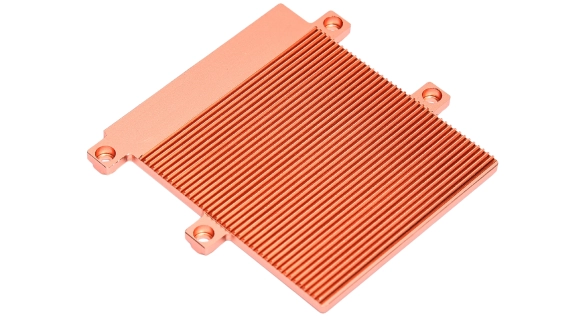
A chamber with excellent spreading performance cannot compensate for an undersized fin stack, poor airflow, or excessive resistance at the chamber-to-sink interface.
Direct Die Contact vs. Substrate Integration
The vapor chamber can be positioned directly beneath the heat source or integrated into a larger structural base.
Direct die contact: The chamber sits close to the semiconductor package, usually through a controlled TIM layer. This reduces intermediate thermal layers and provides a direct path into the chamber.
The mounting design must control surface flatness, contact pressure, and TIM compression. Excessive or uneven loading can damage the package or deform the chamber.
Substrate or baseplate integration: The chamber is installed beneath a structural plate or substrate. This can simplify mechanical mounting and distribute loads, but the additional material layers may increase thermal resistance.
Choose between these configurations based on package construction, electrical isolation requirements, mechanical loading, available space, and the thermal resistance budget.
Fin Stack, Vapor Chamber Base, and TIM Stack-Up
In an air-cooled assembly, the typical thermal path is:
Heat source → TIM → Vapor chamber → Bonding interface or TIM → Fin stack → Airflow
The vapor chamber spreads heat across the heat sink base so that more of the fin area can participate in heat rejection.
However, the fin stack must match the thermal load. Insufficient airflow, excessive fin spacing restrictions, or an undersized heat sink can raise condenser temperature and limit the chamber’s performance.
Review these parameters together:
- Chamber footprint and fin stack dimensions.
- Contact area between the chamber and fin base.
- Bonding method and interface thickness.
- Airflow direction and fan operating conditions.
- Air-side pressure drop and acoustic limits.
- Fin spacing, height, and available air volume.
For liquid-cooled assemblies, the same principle applies. The chamber must transfer heat into a cold plate or another downstream structure with sufficient coolant flow and heat rejection capacity.
One-Piece vs. Two-Piece Structures
The choice between an integrated structure and a separate vapor chamber and heat sink affects thermal resistance, manufacturing, and serviceability.
One-piece integrated structures combine the chamber and cooling structure into a closely integrated assembly. They can reduce the number of separate interfaces and simplify the thermal path.
The trade-off is manufacturing complexity. Material selection, joining, inspection, and repair may become more difficult when the components are integrated.
Two-piece structures use a separate vapor chamber and heat sink connected through a mechanical or bonded interface.
This allows each component to be manufactured and inspected separately. It also provides more flexibility when selecting chamber and fin materials.
The additional interface can increase thermal resistance, so bonding quality and contact area must be controlled.
Compare the two structures using total thermal resistance, production yield, mechanical reliability, assembly cost, and service requirements.
Wick Design: Mesh, Sintered, Grooved, and Hybrid Structures
The wick determines how effectively liquid returns to the evaporator. Its structure influences capillary pressure, permeability, and the chamber’s ability to operate under different orientations and heat loads.
- Mesh wick: Uses woven metal mesh layers. It offers a relatively straightforward construction, but performance depends on mesh size, layer arrangement, and contact with the enclosure.
- Sintered wick: Uses bonded porous metal powder. Fine pores can generate high capillary pressure, making sintered structures useful for demanding heat loads. Permeability and manufacturing consistency must be carefully controlled.
- Grooved wick: Uses channels formed along the internal surface to guide liquid return. Grooves can provide relatively low flow resistance, although their capillary pressure may be lower than that of fine porous structures.
- Hybrid wick: Combines two or more structures to balance capillary pressure and liquid flow. It can be useful when a single wick type cannot meet the required operating conditions.
For example, a design requiring strong capillary return against gravity may favor a different wick structure from a chamber operating horizontally under a lower heat load.
Wick selection should follow the heat source geometry, operating orientation, chamber thickness, working temperature, and required transport capacity. There is no universally best wick type.
7. Manufacturing Realities and DFM Constraints
Manufacturing quality directly affects vapor chamber performance. Enclosure deformation, poor sealing, inconsistent wick construction, or incorrect fluid charging can all reduce thermal capacity. For background on related metal forming and joining methods, see our guide to heat sink manufacturing processes.
These details should be reviewed before tooling and prototype approval, not after a chamber fails testing.
Envelope Materials and Wall Thickness
Copper is widely used for vapor chamber envelopes because of its thermal conductivity, established joining processes, and compatibility with common working fluids.
Material selection must also account for the wick, working fluid, corrosion behavior, and joining process. Changing the envelope material without reviewing the internal system can create compatibility problems.
Wall thickness involves a trade-off:
- Thinner walls: Help reduce package thickness and can reduce conduction resistance through the enclosure, but are more susceptible to deformation during joining and mounting.
- Thicker walls: Improve structural stiffness but consume package space and may increase thermal resistance through the enclosure.
Before design release, define:
- Envelope material and grade.
- Nominal wall thickness and tolerance.
- Surface flatness after joining.
- Internal support requirements.
- Working fluid compatibility.
- Allowable mechanical loads.
The manufacturer should confirm that the proposed thickness can withstand the joining process, internal pressure conditions, and external mounting loads.
Joining, Sealing, and Leak Rate Requirements
A vapor chamber must maintain its sealed internal environment throughout its intended service life.
The enclosure is commonly assembled through brazing, welding, or another qualified joining process. The choice depends on material, wall thickness, chamber geometry, and production requirements.
Joining defects can cause leakage or internal contamination. Excessive heat during joining can also distort thin enclosure walls and affect final dimensions.
After enclosure assembly, the chamber undergoes evacuation, working fluid charging, and final sealing. Non-condensable gases must be controlled because they can interfere with condensation in cooler regions.
When evaluating a supplier, ask:
- Which joining process is used?
- How is the sealing process controlled?
- Which leak detection method is applied?
- What leak rate or acceptance criterion is specified?
- How are defective units identified and rejected?
Leak rate requirements should be defined according to the chamber design, internal conditions, working fluid, and expected service life. A general statement that the product is vacuum sealed is not sufficient qualification data.
Working Fluid Selection and Charging Quantity
The working fluid must match the chamber’s operating temperature range and internal materials.
Water is commonly used in electronics cooling because of its favorable thermophysical properties within suitable operating conditions. Other fluids may be considered when the application requires a different temperature range or material compatibility.
Charging quantity is just as important as fluid selection.
- Insufficient charge: Can leave the wick without enough liquid during operation, causing premature dry-out.
- Excessive charge: Can occupy too much internal volume, reducing the available vapor space and affecting vapor movement or startup behavior.
The correct charge depends on internal volume, wick porosity, working temperature, and chamber geometry.
For a custom design, the manufacturer should establish the charge quantity through engineering calculations, process validation, and prototype testing.
Reliability: Thermal Cycling, Aging, and Orientation Sensitivity
Reliability testing should reflect the actual conditions in which the chamber will operate.
Repeated temperature changes cause the enclosure and internal materials to expand and contract. Mechanical loads, vibration, and unfavorable orientations can introduce additional stress.
Important validation areas include:
- Thermal cycling: Exposes the chamber to defined high and low temperatures to check structural integrity and performance stability.
- Leak testing: Confirms that the enclosure maintains its specified sealing performance.
- Thermal performance aging: Compares thermal resistance and temperature distribution before and after environmental testing.
- Orientation testing: Measures performance in the intended installation directions, especially where liquid return must work against gravity.
- Mechanical testing: Evaluates deformation, mounting loads, and application-specific vibration or shock conditions.
Define test temperatures, cycle counts, dwell times, mounting conditions, and acceptance criteria before qualification begins.
Do not rely on a generic service-life claim. Actual service life depends on sealing quality, material compatibility, operating temperature, fluid stability, and mechanical conditions.
8. How to Specify and Evaluate a Vapor Chamber Supplier
A supplier should demonstrate more than the ability to manufacture a sealed enclosure. It must show that the chamber can meet the required thermal performance, mechanical tolerances, and production reliability.
What a Qualified Vapor Chamber Datasheet Should Include
A useful datasheet should provide enough information to compare the chamber with the system requirements.
- External dimensions: Length, width, thickness, and dimensional tolerances.
- Materials: Envelope material, wick material, and working fluid.
- Thermal performance: Thermal resistance or temperature difference under defined test conditions.
- Operating limits: Recommended temperature range, heat input, and installation orientation.
- Heat transport capacity: Maximum validated heat load and the conditions used to establish it.
- Mechanical specifications: Flatness, surface finish, deformation limits, and mounting requirements.
- Internal construction: Wick type, vapor space, and relevant structural details.
- Reliability results: Leak testing, thermal cycling, and other application-specific validation data.
- Quality controls: Inspection methods, production controls, and acceptance criteria.
Pay particular attention to thermal test conditions. A thermal resistance value without heat input, measurement locations, orientation, and cooling conditions cannot be compared reliably with another supplier’s data.
Five Questions to Ask Before Tooling
Before approving a custom design or committing to tooling, ask the supplier five specific questions.
-
Can you validate the required heat load and heat flux?
Request thermal test data or simulation results that match the intended application. Confirm performance at peak power, maximum operating temperature, and the most demanding installation orientation.
-
Why is this wick structure suitable for the application?
Ask why the proposed mesh, sintered, grooved, or hybrid structure was selected. The supplier should explain how it balances capillary pressure and permeability under the required operating conditions.
-
What are the mechanical limits of the chamber?
Confirm thickness, flatness, wall deformation, allowable clamping pressure, mounting restrictions, and areas that must remain free from external compression.
-
How will sealing and reliability be verified?
Request the joining process, leak detection method, fluid charging controls, and environmental qualification plan. Confirm the acceptance criteria for each test.
-
What changes are required between prototype and mass production?
Discuss tooling, process capability, dimensional repeatability, inspection methods, production yield, and the conditions under which a design change requires requalification.
Prototype-to-Mass-Production Transition Risks
A prototype that meets the thermal target does not automatically prove that the production process is ready.
Small prototype batches may involve manual adjustments and additional inspection. Mass production requires repeatable control over enclosure forming, joining, wick placement, evacuation, fluid charging, and final sealing.
Review five areas before production release:
- Dimensional variation: Changes in thickness, flatness, or overall dimensions can affect assembly fit and thermal contact.
- Joining consistency: Variations in brazing or welding can affect sealing quality and enclosure deformation.
- Wick consistency: Differences in pore structure, porosity, or placement can change liquid return performance.
- Charging variation: Inconsistent working fluid quantities can produce differences in thermal behavior.
- Inspection capability: Production inspection must detect defects affecting vacuum integrity, dimensions, and thermal performance.
Before approving mass production, require evidence that the process can consistently meet the agreed specifications.
Changes to envelope materials, wick construction, joining parameters, working fluid, or production location should be reviewed through an engineering change and requalification process.
Vapor Chamber Prototype Acceptance Checklist
Use the following checklist when evaluating a prototype:
- External dimensions and thickness meet the drawing requirements.
- Flatness and surface condition meet the specified tolerances.
- Mounting interfaces fit the mechanical assembly.
- Thermal resistance meets the agreed test target.
- Maximum component temperature remains within the design limit.
- Temperature distribution across the chamber is acceptable.
- Performance is verified in the intended installation orientations.
- Leak testing meets the specified acceptance criteria.
- Thermal cycling and required environmental tests are complete.
- Assembly pressure does not cause unacceptable deformation.
- Test results are documented against the correct prototype configuration.
Approve the prototype against measurable requirements, not visual inspection or a single temperature reading. For a broader supplier comparison framework, see what buyers should compare in a custom heat sink manufacturer.
9. FAQ: Engineers Actually Search These
Can a Vapor Chamber Work in Any Orientation?
No. A vapor chamber may operate in several orientations, but its heat transport capacity can change depending on how gravity affects liquid return.
When gravity assists condensate return, liquid can reach the evaporator more easily. When the wick must move liquid against gravity, it needs sufficient capillary pressure to overcome the additional resistance.
For equipment that operates vertically, horizontally, or in multiple mounting positions, test the chamber in the most demanding orientation. Horizontal test data alone may not represent actual operating performance.
Are Vapor Chambers in Smartphones the Same as Those Used in Servers?
They use the same evaporation-condensation principle, but their construction and operating requirements differ.
Smartphone vapor chambers are designed around very thin packaging, limited internal space, and compact heat sources. Server vapor chambers may have larger footprints, different wick structures, higher heat loads, and more demanding mechanical integration requirements.
The technology is the same. The dimensions, internal structure, and thermal design are application-specific.
How Long Does a Vapor Chamber Last?
There is no single service-life figure that applies to every vapor chamber.
Its lifespan depends on enclosure sealing, material compatibility, working fluid stability, operating temperature, thermal cycling, and mechanical loading.
For server and industrial applications, request documented leak testing, thermal cycling results, and performance measurements after environmental qualification. These provide a more useful basis for reliability evaluation than an unsupported lifetime claim.
Can a Vapor Chamber Be Repaired?
Most sealed vapor chambers are not designed for field repair.
If the enclosure leaks, loses working fluid, or suffers internal structural damage, restoring its original vacuum environment and fluid charge requires specialized manufacturing equipment.
Replacement is generally more practical than repair. This makes sealing quality, mechanical protection, and reliability testing important before the chamber enters service.
How Much More Does a Vapor Chamber Cost Than a Heat Pipe?
A custom vapor chamber generally costs more than a standard heat pipe because its planar enclosure, internal wick, sealing process, and dimensional requirements can involve more complex manufacturing.
The actual difference depends on chamber dimensions, materials, internal construction, production volume, and testing requirements.
However, comparing individual component prices can be misleading. A vapor chamber may reduce the number of heat pipes, mounting components, or intermediate interfaces required in a complete cooling assembly.
Compare the total system cost, including manufacturing, assembly, thermal performance, and reliability—not just the purchase price of the cooling component.
10. Next Step: Turn Your Thermal Requirements into a Vapor Chamber Design
Custom vapor chamber development starts with the heat load, source dimensions, available installation space, and required operating conditions. These inputs determine the chamber geometry, wick structure, enclosure design, and manufacturing process.
Our engineering team can review your thermal and mechanical requirements and discuss a suitable vapor chamber configuration for your cooling assembly. Explore our custom thermal management solutions for high power electronics to see how vapor chambers fit into complete cooling assemblies.
Planning a custom vapor chamber? Contact our engineering team to discuss your project and request a design review.
To speed up the initial evaluation, prepare your heat source dimensions, power consumption, target chamber thickness, installation orientation, heat sink layout, and thermal performance requirements. A specification sheet covering these details provides a clear starting point for design and quotation.