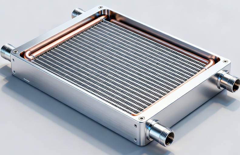
A heat pipe heat sink is used when a standard metal heat sink cannot spread heat fast enough from a concentrated high-power source. By combining a metal base, embedded heat pipes, and fin structures, the design can move heat away from hot components and distribute it across a larger cooling area.
For high power electronics, the challenge is rarely only “how large should the heat sink be?” The more important question is: where is the heat generated, how fast must it be transported, and how evenly can it be spread before airflow removes it?
This is why heat pipe heat sinks are commonly considered for power modules, converters, telecom equipment, industrial electronics, LED systems, laser devices, and compact assemblies where heat density is high but available space is limited.
A well-designed heat pipe heat sink should not be treated as a simple metal part with pipes added later. The heat pipe route, base contact area, fin orientation, airflow direction, mounting pressure, thermal interface material, and operating position all affect final cooling performance. For buyers and engineers, understanding these design points helps reduce prototype failures, avoid oversized structures, and communicate requirements clearly with a thermal supplier.
For custom projects, Jindu Tech provides custom heat pipe heat sink solutions for applications where heat spreading, compact structure, and thermal performance need to be balanced.
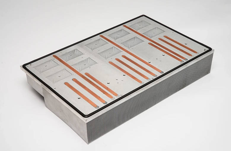
Start with the Heat Source, Not the Heat Sink Shape
The first design step is to define the heat source. In many failed heat sink projects, the cooling structure is selected before the thermal load is properly understood. This often leads to oversized fins, poor heat pipe placement, or uneven component temperatures.
A heat pipe heat sink should be designed around these basic thermal inputs:
| Design Input | Why It Matters |
| Heat source power | Determines total heat that must be transferred away from the component |
| Heat source size | A small high-power chip creates higher heat flux than a larger module with the same wattage |
| Maximum case or junction temperature | Defines the thermal target and allowable temperature rise |
| Ambient temperature | Affects the temperature difference available for cooling |
| Airflow condition | Determines how much heat the fin area can reject |
| Mounting orientation | Can affect heat pipe performance depending on the internal wick and gravity direction |
| Space envelope | Limits heat pipe bending, fin height, base size, and assembly method |
For high power electronics, heat density is often more important than total wattage. A 200 W module spread across a large base may be easier to cool than an 80 W device concentrated in a small footprint. Heat pipes are valuable when the heat source is localized and the cooling area must be moved or expanded.
Before selecting a heat pipe heat sink, engineers should calculate or estimate the required thermal resistance from the component to ambient. This does not need to be perfect at the early stage, but it should be realistic enough to guide the design direction.
When a Heat Pipe Heat Sink Makes Engineering Sense
A heat pipe heat sink is not necessary for every electronic product. In low-power systems, a simple extruded aluminum heat sink may be more economical and easier to manufacture. Heat pipes become more useful when heat must be transported laterally, spread quickly, or moved away from a restricted component area.
Typical situations include:
- A high-power chip or module creates a local hotspot.
- The available fin area is not directly above the heat source.
- A pure aluminum heat sink becomes too large or too heavy.
- Airflow is available in one area, but the heat source is located elsewhere.
- Temperature uniformity is more important than simple heat removal.
- The product has a narrow or irregular internal space.
- The design needs passive or low-noise cooling with limited fan speed.
| Cooling Requirement | Standard Aluminum Heat Sink | Heat Pipe Heat Sink |
| Low to medium heat load | Usually suitable | May be unnecessary |
| Localized high heat flux | May develop hotspots | Better heat spreading |
| Limited space above component | Often difficult | Heat can be moved to a remote fin area |
| Weight-sensitive design | Can become bulky | Can reduce the need for thick copper bases |
| Complex internal structure | Limited flexibility | Heat pipes can be routed depending on design limits |
| High temperature uniformity | Less effective over long distances | Stronger heat distribution across the fin base |
A heat sink with heat pipe is especially useful when the design problem is not only “remove heat,” but “move heat from where it is generated to where it can be dissipated.”
How Heat Pipe Cooling Works Inside the Assembly
A heat pipe transfers heat through a sealed phase-change cycle. Heat enters the evaporator section near the hot component. The working fluid inside the pipe vaporizes and moves toward a cooler condenser section. There, the vapor releases heat and condenses back into liquid. The wick structure then helps return the liquid to the hot region.
This internal cycle allows heat pipes to transfer heat efficiently over a distance. In a heat pipe heat sink, the pipes are usually embedded, pressed, soldered, or bonded into a base structure so they can collect heat from the source and distribute it to fins or a larger cooling surface.
The assembly typically includes:
- A base plate that contacts the electronic component
- One or more heat pipes embedded or attached to the base
- Fins that increase surface area for air cooling
- A thermal interface area for contact with the device
- Mounting holes, screws, clips, or brackets
- Surface treatment depending on corrosion, insulation, or appearance requirements
The thermal path usually follows this sequence:
Component → thermal interface material → heat sink base → heat pipe evaporator section → heat pipe condenser section → fin area → air
Every interface in this path adds resistance. Even if the heat pipe itself performs well, poor contact between the heat pipe and base can reduce the real cooling result. This is why groove design, bonding quality, flatness, and assembly pressure matter.
Heat Pipe Layout: The Design Choice That Changes Everything
Heat pipe layout is one of the most important parts of custom heat pipe heat sink design. The pipe should collect heat from the source, move it toward a larger dissipation zone, and avoid unnecessary bends or contact gaps.
The best heat pipe layout is the one that places the evaporator section directly under or very close to the main heat source. If the pipe is too far from the hotspot, the base must conduct heat laterally before the heat pipe can help. That weakens the purpose of using heat pipe cooling.
Common layout options include:
| Layout Type | Typical Use | Design Notes |
| Straight heat pipes under fins | Heat source and fin area are aligned | Simple structure, suitable when airflow passes directly through fins |
| U-shaped heat pipes | Heat must spread to both sides | Useful for wider fin fields or central heat sources |
| Flattened heat pipes in base | Low-profile electronics | Requires careful control to avoid damaging internal wick structure |
| Multiple parallel heat pipes | Higher power density | Helps spread heat more evenly across a larger base |
| Remote condenser layout | Heat source and cooling area are separated | Useful when airflow is available away from the component |
The number of heat pipes should not be chosen only by total power. It depends on heat pipe diameter, length, orientation, allowable temperature rise, contact area, and how evenly the source power is distributed. In many applications, two well-positioned heat pipes can outperform several poorly placed ones.
Engineers should also consider whether the product will operate horizontally, vertically, or in multiple orientations. Although many modern heat pipes use wick structures that reduce gravity dependence, orientation can still influence performance depending on design and application conditions.
Base Design: Flatness, Contact Area, and Heat Spreading
The base is the transition zone between the electronic component and the heat pipe system. If this zone is poorly designed, the heat pipe heat sink may not perform as expected.
Several base design points deserve attention:
| Base Design Point | Engineering Impact |
| Contact flatness | Improves contact with the component or thermal interface material |
| Base thickness | Affects heat spreading before heat reaches the pipes |
| Groove accuracy | Helps maintain contact between heat pipe and base |
| Material selection | Balances conductivity, weight, machinability, and cost |
| Mounting pressure | Influences thermal interface resistance |
| Surface finish | Affects contact quality and corrosion resistance |
A thicker base can improve heat spreading, but it also adds weight and material cost. A thinner base saves space and weight, but may not spread heat effectively before it reaches the heat pipes. The right design depends on the heat source footprint and the distance between the heat source and pipe location.
For many high power heat sink projects, aluminum is commonly used for the base and fins because it offers a practical balance of thermal performance, weight, and manufacturability. Copper may be used in selected areas when higher local conductivity is required, but a full copper structure can become heavy and expensive.
A custom design should match the base structure to the real thermal map of the device rather than simply adding more material.
Fin Design and Airflow Must Match the Heat Pipe Strategy
A heat pipe moves heat. The fins reject heat. If the fin design is weak, the heat pipe cannot solve the whole thermal problem.
Important fin design questions include:
- Is the airflow natural convection or forced air?
- What is the airflow direction?
- Is fan pressure high enough for dense fin spacing?
- Will dust, vibration, or outdoor exposure affect fin performance?
- Is the heat sink installed in an enclosure?
- Is acoustic noise a concern?
- Is the fin field located directly above the heat source or away from it?
In forced-air systems, fin spacing can often be tighter because airflow is driven by a fan. In natural convection systems, fins usually need more open spacing to allow warm air to rise and escape. For compact electronics, the fin direction should match the actual air path inside the product.
Heat pipes do not replace the need for proper airflow design. They only help deliver heat to the cooling area. If hot air is trapped inside the enclosure, the thermal performance will still be limited.
This is why early mechanical and thermal coordination is important. The heat sink supplier should understand not only the component power, but also the housing, fan position, nearby components, and installation direction.
Engineering Decision Matrix for Heat Pipe Heat Sink Design
The following matrix can help engineers and buyers decide which design direction may fit their application.
| Application Condition | Recommended Design Direction |
| Heat source is small and high-power | Use heat pipes close to the source with strong base contact |
| Heat source is far from available airflow | Consider remote heat pipe routing to a fin area |
| Product height is limited | Use flattened heat pipes and low-profile fin structures if feasible |
| Weight must be reduced | Avoid oversized copper blocks; use aluminum base with heat pipe assistance |
| Multiple heat sources exist | Use shared base design or multiple heat pipe paths depending on thermal map |
| Natural convection is required | Use more open fin spacing and larger surface area |
| Strong forced airflow is available | Higher fin density may be possible depending on pressure drop |
| Outdoor or harsh environment | Consider surface treatment, corrosion resistance, and mechanical reliability |
This matrix should not replace thermal simulation or prototype validation, but it gives a practical starting point for early communication.
Quality Risks That Can Reduce Real Thermal Performance
A heat pipe heat sink may look simple from the outside, but its performance depends on several hidden details. Buyers should pay attention to quality risks during supplier evaluation.
Common risks include:
| Risk | Possible Result | What to Check |
| Poor contact between heat pipe and base | Higher thermal resistance | Ask how pipes are embedded, bonded, or soldered |
| Excessive heat pipe flattening | Reduced internal flow performance | Confirm forming limits and inspection method |
| Inaccurate groove machining | Air gaps or weak bonding | Check machining capability and dimensional control |
| Uneven base flatness | Poor contact with component | Request flatness requirements based on your mounting design |
| Weak soldering or adhesive bonding | Performance drift or mechanical failure | Ask about bonding process and inspection |
| Wrong fin orientation | Poor airflow utilization | Confirm assembly direction and airflow path |
| Insufficient prototype testing | Late-stage thermal failure | Use thermal testing before mass production |
For high power electronics, small interface problems can create large temperature differences. A heat pipe with good theoretical performance may underperform if the assembly process is not controlled.
What to Prepare Before Requesting a Custom Heat Pipe Heat Sink
A supplier can respond more accurately when the buyer provides clear engineering information. A vague request such as “we need a heat sink for 300 W” is not enough because thermal performance depends heavily on structure, airflow, and allowable temperature.
Before requesting a quotation, prepare the following information:
| RFQ Information | Example of What to Provide |
| Heat source power | Total wattage and power distribution |
| Heat source dimensions | Component size, contact area, module footprint |
| Temperature target | Maximum case temperature or allowable temperature rise |
| Ambient condition | Operating temperature range and enclosure condition |
| Airflow details | Natural convection, fan airflow, air direction, fan position |
| Space limits | Maximum length, width, height, and keep-out zones |
| Mounting method | Screw holes, clips, pressure requirements, insulation needs |
| Orientation | Horizontal, vertical, or variable installation direction |
| Surface requirements | Anodizing, plating, insulation, corrosion resistance if needed |
| Files | 2D drawings, 3D models, PCB layout area, or mechanical envelope |
The more clearly the thermal boundary conditions are defined, the easier it is to design a heat pipe heat sink that matches the real application. This reduces repeated design changes and helps the supplier suggest a practical structure.
If your design is still in the early stage, you can still contact Jindu Tech with preliminary power, size, and application information. The design can then be refined as mechanical drawings and thermal targets become clearer.
Prototype Validation: Do Not Skip the Thermal Test
Even with simulation and careful design, prototype testing is still important. High power electronics often operate in complex environments where airflow, contact pressure, cable routing, enclosure design, and nearby heat sources can affect temperature.
Useful validation methods include:
- Thermal resistance testing under controlled power load
- Temperature measurement at the heat source, base, and fin area
- Infrared thermal imaging to identify hotspots
- Airflow testing inside the enclosure
- Mounting pressure and thermal interface verification
- Vibration or mechanical checks if the product is used in harsh conditions
- Long-duration power testing under realistic ambient conditions
The goal is not only to confirm peak temperature. Engineers should also check whether heat is spreading evenly across the base and fins. If one area is much hotter than the rest of the heat sink, the heat pipe layout or contact design may need adjustment.
Prototype testing is also the right stage to optimize cost. Sometimes the first design uses extra material or more heat pipes for safety. After test data is available, the structure may be simplified without sacrificing required thermal performance.
Heat Pipe Heat Sink vs Liquid Cold Plate: When to Reconsider the Cooling Method
Heat pipe heat sinks are often used for air-cooled systems, but some high-power electronics may eventually require liquid cooling. The decision depends on heat load, available airflow, noise limits, enclosure size, and reliability requirements.
| Cooling Method | Better Fit |
| Standard heat sink | Lower heat load, simple structure, cost-sensitive products |
| Heat pipe heat sink | Local hotspots, compact structure, remote heat spreading, air cooling |
| Liquid cold plate | Very high heat density, limited airflow, strict temperature control |
A heat pipe heat sink can extend the capability of air cooling, but it does not make airflow unlimited. If the product has very high heat density and little air movement, a liquid cold plate may be more suitable. However, liquid cooling adds pump, fluid, sealing, maintenance, and system integration considerations.
For many industrial and electronic applications, heat pipe cooling offers a useful middle ground: stronger heat spreading than a standard heat sink, but simpler system integration than liquid cooling.
Supplier Evaluation Questions for High Power Heat Sink Projects
When evaluating a custom heat pipe heat sink supplier, buyers should ask engineering-focused questions instead of only comparing unit price.
Useful questions include:
- How will the heat pipes be positioned relative to the heat source?
- What base material and thickness do you recommend for this power density?
- Can the design fit within the available mechanical envelope?
- How will the heat pipe be bonded or fixed into the base?
- What inspection steps are used for heat pipe contact and assembly quality?
- Can you support prototype adjustment after thermal testing?
- What information do you need before providing a reliable quotation?
- How should airflow direction and fin orientation be coordinated?
- Are there surface treatment options for corrosion or insulation needs?
- What drawings or 3D files should be provided before production?
These questions help separate a true custom thermal design discussion from a simple parts quotation. For high power electronics, supplier communication should focus on thermal path, manufacturability, testing, and risk control.
Conclusion: Design the Thermal Path Before Designing the Metal Shape
A heat pipe heat sink is most effective when it is designed as a complete thermal path, not just a metal heat sink with added pipes. The heat source, base, pipe route, bonding method, fin field, airflow, mounting pressure, and operating environment must work together.
For engineers, the key is to define the heat load and space constraints early. For buyers, the key is to provide enough application information so the supplier can recommend a structure that is realistic for manufacturing and testing.
If your high power electronics project has local hotspots, limited space, or uneven temperature distribution, a heat pipe heat sink may provide a practical way to improve heat spreading while keeping the cooling system compact. Jindu Tech can support custom heat pipe heat sink discussions based on your power level, component layout, mechanical space, and application requirements.
FAQ
What is a heat pipe heat sink used for in electronics?
A heat pipe heat sink is used to move heat away from high-power electronic components and spread it across a larger fin area. It is especially useful when the heat source is small, the available cooling space is limited, or the fin area cannot be placed directly above the component.
Is a heat pipe heat sink better than a regular aluminum heat sink?
It depends on the application. A regular aluminum heat sink may be enough for low or moderate heat loads. A heat pipe heat sink is usually more suitable when there is high heat density, a local hotspot, or a need to transfer heat to a remote cooling area.
How do you design a heat pipe layout for high power electronics?
The heat pipe should be placed close to the main heat source, with a clear thermal path to the fin area. Engineers should consider heat source size, pipe length, bending, orientation, base contact, airflow direction, and available mechanical space before finalizing the layout.
Can heat pipes work in any orientation?
Many heat pipes can work in different orientations because of their internal wick structure, but orientation may still affect performance depending on the design. For critical applications, the expected installation direction should be shared with the supplier and verified during prototype testing.
What information is needed for a custom heat pipe heat sink quotation?
Useful RFQ information includes heat source power, component size, target temperature, ambient temperature, airflow condition, available space, mounting method, operating orientation, surface requirements, and 2D or 3D drawings. These details help the supplier design a more accurate cooling structure.
Does adding more heat pipes always improve cooling performance?
No. More heat pipes do not automatically mean better cooling. Placement, contact quality, pipe capacity, base design, and airflow are more important. In some cases, fewer well-positioned heat pipes can perform better than several poorly integrated pipes.
When should I choose liquid cooling instead of a heat pipe heat sink?
Liquid cooling may be considered when heat density is very high, airflow is limited, or temperature control requirements are strict. A heat pipe heat sink is often a simpler option when air cooling is still possible but better heat spreading is needed.