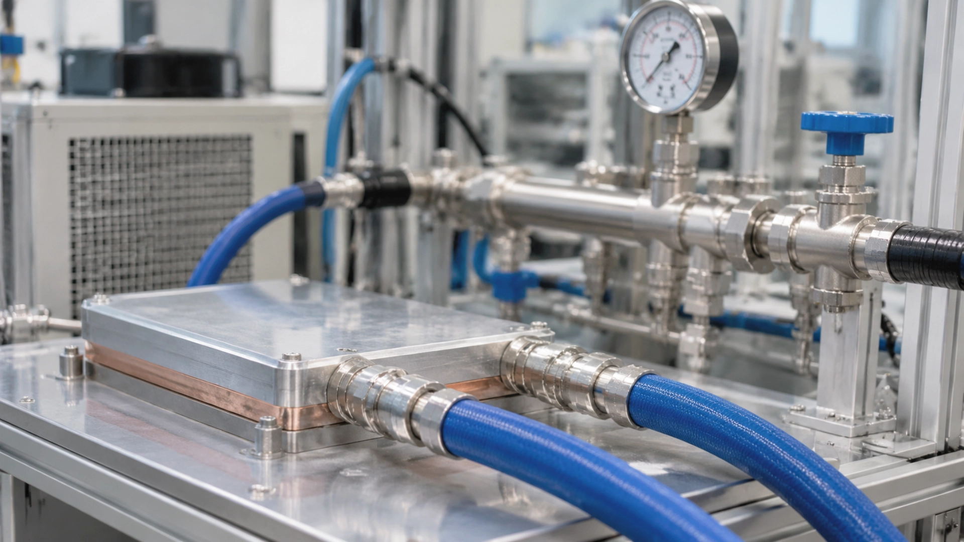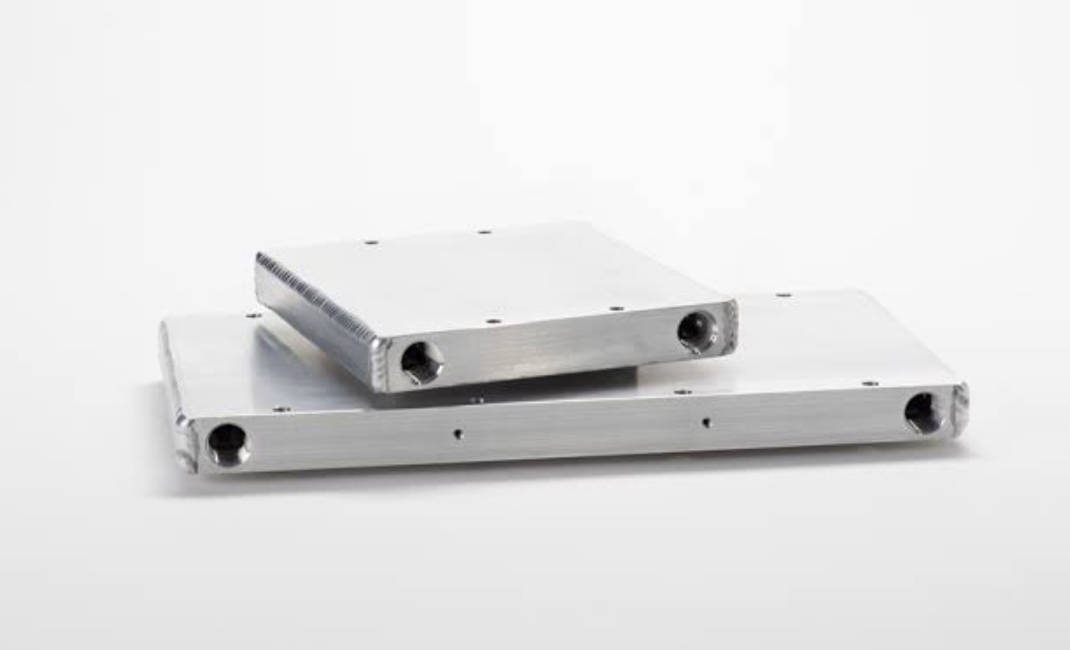
Most modern passenger EVs cool their batteries with liquid. A water-glycol mix runs through cold plates, absorbs heat from the cells, and dumps it at a radiator or chiller. That’s the default—not the only option.

Air cooling still survives in smaller, lower-power packs. Refrigerant, immersion, PCM, and hybrid systems exist because a simple coolant loop can’t solve every thermal problem. The differences are real: heat removal rate, cell-to-cell temperature spread, cost, weight, and maintenance load over the vehicle’s life.
Pick the wrong architecture and you either overspend on hardware you don’t need or under-cool a pack that will derate on every fast charge. The sections below work through each route, then put them side by side.
TL;DR — The 30-Second Answer
Indirect liquid cooling is the mainstream choice. Cold plates move heat from cells into a circulating coolant. A radiator or chiller rejects it. The same loop can heat the pack in cold weather.
Air cooling is cheaper and simpler, but it runs out of capacity fast. Fine for small packs. Repeated DC fast charging or high discharge rates expose its limits quickly.
Refrigerant, immersion, PCM, and heat pipes solve narrower problems. They improve heat transfer, buffer peaks, or cut thermal resistance—each at a cost in fluid compatibility, packaging, or system complexity. Hybrid BTMS combines two approaches when one can’t cover the full operating envelope.
Why EV Batteries Need Thermal Management — The Numbers Behind the Need
A lithium-ion cell only performs well inside a narrow temperature band. Outside it, charging slows, resistance climbs, capacity fades, and in the worst case the cell enters thermal runaway.
A BTMS has three jobs: keep the pack in range, keep cells close to each other in temperature, and heat the pack when ambient is cold.
The Temperature Window: Optimal Range vs. Degradation Onset vs. Thermal Runaway Threshold
Most EV packs target 15–35°C. That’s the sweet spot. Outside it, the numbers get worse in a hurry.
| Temperature | Battery Behavior | Thermal Management Response |
|---|---|---|
| Below 0°C | Charging gets difficult. Lithium plating risk rises under aggressive charging. | Heat the pack or limit charging power. |
| 15–35°C | Normal operating target for most lithium-ion systems. | Maintain uniformity and remove heat generated during operation. |
| 35–45°C | Aging accelerates, especially under sustained load. | Increase cooling capacity. |
| Above 45°C | Degradation and safety margin shrink. | Protective derating or shutdown may be required. |
| Cell-dependent, higher | Exothermic reactions can trigger thermal runaway. | Cell-level protection and propagation control become critical. |
These are engineering reference ranges, not hard limits. Thermal runaway doesn’t start at one fixed temperature—it depends on chemistry, state of charge, cell construction, and the trigger condition.
Average pack temperature also hides problems. A pack can sit at a comfortable average while a handful of cells run 10°C hotter. Most designs target ≤5°C cell-to-cell spread under defined test conditions.
What Heat Does to a Cell: Capacity Fade, Internal Resistance Rise, and Lithium Plating
Heat doesn’t just warm the pack. It accelerates four aging mechanisms at once.
- Capacity fade: High temperature speeds up electrolyte decomposition and SEI growth. Both consume active lithium. Usable capacity drops.
- Resistance rise: Resistance climbs with temperature and age. Higher resistance means more voltage loss and more heat generated during operation—a feedback loop.
- Lithium plating: Charging at low temperature or high rate can deposit metallic lithium on the anode instead of intercalating it. Capacity drops. Safety risk rises.
- Accelerated aging: Repeated high-temperature exposure shortens pack life, especially combined with high state of charge and frequent high-power use.
Cold creates a different problem. Internal resistance rises, charging acceptance falls, and available power is restricted. That’s why a BTMS needs heating as well as cooling.
Why Fast Charging Broke the Old Cooling Assumptions
A cooling loop sized for normal driving won’t keep up with repeated high-power charging. The physics is simple.
Resistive heating follows Q = I²R, where Q is heat generation rate, I is current, and R is resistance. Current is squared. Double the current and you get four times the resistive heat, assuming resistance holds. Real packs also generate electrochemical and polarization heat, so this is only part of the load—but it shows why fast charging stresses cooling so hard.
A 350 kW charger doesn’t deliver 350 kW continuously. Actual power depends on pack voltage, state of charge, cell temperature, and the vehicle’s charging limits. Even so, sustained high power forces the cooling system to remove heat fast—without excessive pressure drop or pumping power.
Preconditioning adds another requirement. Before the car reaches a fast charger, it may heat or cool the pack to bring cells into their preferred charging window. That’s extra thermal work the system has to handle.
Modern BTMS design therefore covers four cases, not one: normal driving, repeated fast charging, cold-weather operation, and temperature spread across the whole pack.
The Classification Tree — Active vs. Passive, Air vs. Liquid, and Everything In Between
Three dimensions sort every EV cooling system on the market: energy source, heat transfer medium, and contact method. The tree below shows how the routes fit together. It’s a simplified map, not a strict hierarchy—some technologies sit on more than one branch.
EV Battery Thermal Management
│
├── Active Cooling
│   │
│   ├── Air Cooling
│   │   ├── Forced-Air Cooling
│   │   └── Active Ventilation
│   │
│   ├── Indirect Liquid Cooling
│   │   ├── Cold Plates
│   │   └── Cooling Channels
│   │
│   └── Refrigerant-Based Cooling
│       ├── Indirect Refrigerant Cooling
│       └── Direct Refrigerant Cooling
│
├── Passive Cooling
│   │
│   ├── Natural Air Convection
│   ├── Phase Change Materials
│   └── Heat Pipes
│
└── Hybrid BTMS
    │
    ├── Liquid + PCM
    ├── Liquid + Heat Pipes
    └── Air + PCM
Immersion cooling sits in the liquid branch but uses direct contact: the dielectric fluid touches cell surfaces. It runs single-phase with a pump and external heat exchanger, or two-phase with evaporation and condensation.
This distinction matters. Two systems both called “liquid cooling” can have completely different thermal interfaces, fluid requirements, sealing, and maintenance procedures. The three tables below unpack each axis.
Axis 1 — Classification by Energy Source
| Category | Working Principle | Typical Technologies |
|---|---|---|
| Active Cooling | Powered components move air, coolant, or refrigerant. | Fans, pumps, compressors, refrigeration circuits. |
| Passive Cooling | Natural heat transfer or thermal storage, no continuous mechanical circulation. | Natural convection, PCM, heat pipes, thermal spreaders. |
Axis 2 — Classification by Heat Transfer Medium
| Cooling Medium | How It Transfers Heat | Typical Application |
|---|---|---|
| Air | Air absorbs heat from battery surfaces and carries it away. | Smaller, lower-power packs. |
| Liquid Coolant | Circulating liquid moves heat from cold plates to a heat exchanger. | Modern passenger EVs, high-power packs. |
| Refrigerant | Refrigerant absorbs heat through a refrigeration cycle or dedicated interface. | Battery systems integrated with vehicle AC. |
| Phase Change Material (PCM) | Absorbs thermal energy during a solid-to-liquid transition. | Passive buffering and hybrid systems. |
| Heat Pipes | Evaporation and condensation of an internal working fluid. | Localized heat spreading. |
Axis 3 — Classification by Contact Method
| Contact Method | Description | Example |
|---|---|---|
| Indirect Cooling | Heat passes through a conductive interface before reaching the cooling medium. | Cells thermally bonded to liquid cold plates. |
| Direct Cooling | Cooling medium directly contacts the battery or its cooling surface. | Dielectric immersion cooling. |
| Direct Refrigerant Cooling | Refrigerant absorbs heat through a dedicated battery circuit. | Refrigerant-based battery architectures. |
Method-by-Method: How Each Cooling Route Actually Works
Six routes. Each one collects heat, moves it, and rejects it differently. The reference ranges below are engineering orientation values, not universal specs—actual numbers depend on cell chemistry, pack geometry, and system design.
1. Indirect Liquid Cooling (Cold Plate + Coolant Loop)
Bottom line: the default for modern passenger EVs. Handles fast charging and normal driving without drama.
Cells sit above, below, or beside cold plates. Channels inside the plates carry water-glycol coolant. Heat moves from cell → housing → thermal interface material → cold plate → coolant → radiator or chiller. The liquid never touches the cells.
How It Works
A typical loop has six parts: cold plates or integrated channels, an electric coolant pump, a reservoir and piping, a radiator or heat exchanger, a chiller when extra refrigeration is needed, and temperature/pressure/flow sensors. The same architecture supports heating through a heater or heat pump.
Key Engineering Parameters
| Parameter | Typical Reference Range | What Engineers Need to Evaluate |
|---|---|---|
| Coolant Type | Water-glycol 30–50% by volume | Heat capacity, conductivity, freezing protection, material compatibility. |
| Coolant Flow Rate | 5–20 L/min per pack loop | Whether flow removes the expected heat load without excessive pump power. |
| Coolant ΔT (outlet − inlet) | 3–8°C under peak load | Flow adequacy and temperature uniformity along the flow path. |
| Cold Plate Thermal Resistance | 0.01–0.05 K/W (cell-to-coolant) | Channel geometry, plate material, contact resistance, coolant properties. |
| Cell-to-Cell ΔT Target | ≤5°C under defined test conditions | Flow balance, manifold design, thermal interface contact. |
| Pressure Drop | 10–50 kPa across the pack loop | Hydraulic resistance and pump requirements. |
| Coolant Inlet Temperature | 15–30°C, set by chiller or radiator control | Whether inlet temperature meets the battery’s requirement. |
Heat removal follows Q = ṁ × Cp × ΔT, where ṁ is mass flow, Cp is specific heat, and ΔT is outlet minus inlet. Higher flow removes more heat and shrinks ΔT across the plate—but raises pumping power and pressure drop. Thermal and hydraulic performance trade off directly. For a detailed look at flow channel design, pressure drop, and thermal performance, see our liquid cold plate design guide.
Typical Applications
Passenger EVs, electric SUVs, performance vehicles, commercial battery systems. Works best when the pack needs high charge/discharge power, tight temperature spread across modules, heating and cooling in one system, and integration with cabin AC or a heat pump.
Limitations
Complexity is the price. Pumps, pipes, seals, valves, and heat exchangers add weight, cost, and failure points.
A coolant leak kills cooling capacity and can damage nearby electronics. Corrosion, contamination, channel blockage, and pump failure all show up as performance loss.
Cold plate design matters more than people expect. A poor channel layout creates uneven flow and leaves some cells hotter than others. Thermal interface materials must stay in contact through temperature cycling and vibration—if they don’t, heat transfer collapses at the worst possible moment.
2. Air Cooling: Passive and Active
Bottom line: cheap, simple, and out of its depth on modern fast-charging packs.
Air cooling uses natural or forced airflow to pull heat off cell surfaces. No coolant circuit, no sealing, fewer parts to maintain.
How It Works
Passive air cooling relies on natural convection. Heat moves from the pack surface into surrounding air without a dedicated fan. Active air cooling uses fans or blowers to push air through channels between cells or modules. Warmed air exits through ventilation paths. Some systems tap conditioned cabin air to help regulate temperature.
Key Engineering Parameters
| Parameter | Typical Reference Range | What Engineers Need to Evaluate |
|---|---|---|
| Airflow Rate | 50–300 m³/h per pack (forced) | How much heat moving air can carry away. |
| Air Inlet Temperature | Ambient or cabin-conditioned, 20–40°C | Hot incoming air shrinks the cooling margin. |
| Air Velocity at Cell Surface | 1–5 m/s (forced) | Convective heat transfer coefficient. |
| Cell-to-Cell ΔT | Often 5–10°C, worse at high ambient | Difference between inlet-side and downstream cells. |
| Air-side Thermal Resistance | 0.1–0.5 K/W (cell-to-air, indicative) | Channel geometry, cell spacing, airflow distribution. |
Typical Applications
Earlier-generation EVs and lower-power battery systems. The Nissan Leaf used passive air-based thermal management in earlier generations. For a modest pack with low heat generation, air cooling does the job without a liquid loop’s cost.
Limitations
Air has far lower thermal conductivity and volumetric heat capacity than water-glycol. Removing serious heat takes large airflow and well-designed channels.
Performance depends on ambient. On a 40°C day, incoming air is already too warm to cool effectively. Cells near the inlet get cooler air than cells downstream.
Dust blocks passages. Fans degrade. Ventilation adds noise. These limits make air cooling a poor fit for high-energy-density packs and vehicles that use DC fast charging regularly. For a direct comparison of liquid and air cooling in high-power electronics, see our liquid vs air cooling guide.
3. Direct Liquid / Refrigerant Cooling
Bottom line: strong when the battery can share the vehicle’s AC circuit. Weak when the cabin wants the same cooling capacity at the same time.
Refrigerant-based cooling taps the vehicle’s refrigeration loop to absorb battery heat. It is not the same as dielectric immersion—refrigerant runs through a sealed circuit and absorbs heat at a battery evaporator or cooling plate.
How It Works
Refrigerant absorbs heat through a battery cooling plate, evaporator, or dedicated interface. As it changes state in the refrigeration cycle, it pulls thermal energy out of the battery. A compressor, condenser, expansion device, and heat exchangers control the process. The BMW i3 is a production example—its battery thermal management uses refrigerant from the vehicle AC system.
Key Engineering Parameters
| Parameter | Typical Reference Range | What Engineers Need to Evaluate |
|---|---|---|
| Refrigerant Type | R-134a, R-1234yf, or R-744 (CO₂) | Boiling temperature, latent heat, pressure, material compatibility. |
| Evaporating Temperature | 5–20°C at the battery evaporator | Temperature at which refrigerant absorbs battery heat. |
| Refrigerant Mass Flow | 0.02–0.1 kg/s (indicative) | Available cooling capacity for the battery circuit. |
| Latent Heat of Vaporization | 150–250 kJ/kg (typical HFC/HFO) | Heat absorbed per unit mass during phase change. |
| Battery-Side Thermal Resistance | 0.01–0.04 K/W (indicative) | Heat exchanger performance and refrigerant distribution. |
| Operating Pressure | Design-dependent; must stay within refrigeration limits | Circuit safety and control range. |
Typical Applications
Useful when the OEM wants battery thermal control integrated with the existing AC system. Depending on architecture, this can eliminate a separate secondary coolant circuit and still deliver strong cooling under load.
Limitations
Battery and cabin both want cooling at the same time—hot-weather driving plus fast charging is the worst case. The refrigeration system has to split capacity between them without compromising either.
Refrigerant leaks, pressure control, circuit complexity, and service requirements all need attention. Refrigerant choice also has to satisfy thermal performance, environmental regulation, and long-term availability.
4. Immersion Cooling
Bottom line: the best heat transfer per unit of contact resistance, wrapped in the most packaging and service headaches.
Immersion cooling submerges cells or battery components in a dielectric liquid. The fluid touches cell surfaces directly and absorbs heat without conducting electricity under specified operating conditions.
How It Works
Single-phase: the dielectric liquid absorbs heat and stays liquid. A pump circulates heated fluid through an external heat exchanger, where heat transfers to another circuit or the environment.
Two-phase: the liquid absorbs heat and boils at its boiling point. Vapor travels to a condenser, releases heat, and returns to liquid. Two-phase systems use latent heat of vaporization for high heat transfer—at the cost of more demanding design and control.
Key Engineering Parameters
| Parameter | Typical Reference Range | Why It Matters |
|---|---|---|
| Electrical Resistivity | >10¹² Ω·cm (indicative) | Fluid must maintain insulation under operating conditions. |
| Specific Heat Capacity | 1.5–2.5 kJ/(kg·K) for fluorinated fluids | How much heat the liquid absorbs before temperature rises. |
| Thermal Conductivity | 0.06–0.10 W/(m·K) for fluorinated fluids | Heat transfer between cell surfaces and fluid. |
| Viscosity | 0.5–5 mPa·s (varies strongly with temperature) | Pumping power and fluid distribution. |
| Boiling Point (two-phase) | 50–100°C depending on fluid | Operating temperature range of two-phase systems. |
| Latent Heat (two-phase) | 80–150 kJ/kg (indicative) | Heat transported per unit mass during evaporation. |
| Material Compatibility | Fluid-specific; requires long-term testing | Whether fluid can contact seals, cables, adhesives, and cell materials safely. |
No single dielectric fluid fits every battery design. Engineers have to weigh thermal properties, insulation, chemical stability, environmental rules, and compatibility with the full battery assembly.
Typical Applications
Under investigation for performance EVs, specialized commercial vehicles, and energy storage. Frequently compared with data center practice, where immersion cooling already cools electronics with insulating liquids. Automotive adds vibration, impact, thermal cycling, crash conditions, and long service intervals—a fluid that works in a stationary rack may not survive a vehicle.
Limitations
Fluid cost, system mass, material compatibility, and serviceability are the main blockers. Large packs need large fluid volumes. Viscous fluids raise pumping power. Two-phase systems need reliable vapor containment and condensation.
Seals, insulation, adhesives, and cell materials must survive long-term fluid exposure. Immersion cuts thermal resistance—but that gain has to justify the added cost and complexity of the full system.
5. Phase Change Materials and Heat Pipes
Bottom line: good at buffering short peaks and spreading local heat. Not a replacement for active cooling in a high-power pack.
PCM and heat pipes work by different mechanisms, but both manage heat without a conventional circulating coolant loop.
How They Work
PCM absorbs heat as it melts from solid to liquid. During the transition, it stores latent heat without a matching temperature rise. PCM sits around cells or modules; when the pack generates heat, the material absorbs part of the load and slows the temperature climb.
Heat pipes use a sealed chamber with a working fluid. Heat at one end evaporates the fluid. Vapor travels to a cooler section, condenses, and releases heat. Liquid returns through a wick or other mechanism. No mechanical pump inside the pipe.
Key Engineering Parameters
| Parameter | PCM Typical Range | Heat Pipe Typical Range |
|---|---|---|
| Latent Heat / Transport Capacity | 150–250 kJ/kg | 10–100 W per pipe (design-dependent) |
| Melting / Operating Temperature | 25–45°C (tuned to battery window) | 20–60°C working fluid range |
| Thermal Conductivity | 0.2–1.0 W/(m·K) base; 1–10 W/(m·K) with additives | Effective conductivity orders of magnitude higher than copper |
| Structural Requirement | Expansion allowance, leak-resistant containment | Wick structure, internal pressure, sealing integrity |
| Long-Term Reliability | Phase-change cycling stability | Working fluid stability and internal sealing |
Typical Applications
PCM suits short bursts of high heat—it absorbs part of the load and delays temperature rise. Heat pipes suit localized hot spots that need to move heat to a larger rejection surface. Both support modules, compact designs, and hybrid systems.
Limitations
PCM stores heat. It doesn’t remove it. Once the material melts, remaining capacity is limited until it releases heat and solidifies again. Low thermal conductivity also slows heat movement through the PCM—metal fins or graphite additives help.
Heat pipes have their own limits. Performance depends on working fluid, orientation, internal pressure, wick design, and maximum transport capacity. Neither technology replaces active cooling in a high-power EV without a full thermal load assessment.
6. Hybrid BTMS
Bottom line: makes sense when one technology can’t cover both the transient peak and the sustained load. Otherwise it’s added cost for added complexity.
A hybrid BTMS combines two or more technologies. The goal: let each component handle the part of the thermal load it does best.
How It Works
One common layout pairs liquid cooling with PCM. PCM absorbs short-term peaks near the cells; the liquid loop removes accumulated heat over longer periods. Another pairs heat pipes with cold plates—heat pipes spread local heat across a larger area, cold plates move it into coolant. Others combine forced air with PCM or use different methods for different modules.
Key Engineering Parameters
- Thermal load split: passive element typically buffers 20–40% of peak heat during transients; active loop handles the rest.
- Response time: active loop responds in seconds to tens of seconds; PCM buffering lasts minutes.
- Temperature uniformity: hybrid designs often target ≤3–5°C cell-to-cell ΔT.
- Thermal storage capacity: sized to cover one fast-charging peak or a short high-power acceleration event.
- System integration: packaging, interfaces, and control logic must coordinate active and passive elements.
- Energy consumption: pumps, fans, compressors—the passive element can cut active-loop duty cycle.
Typical Applications
Performance EVs, high-power packs, commercial vehicles, and any pack with large swings in thermal load. Useful when a conventional liquid loop can’t handle short thermal peaks efficiently, or when localized hot spots need extra heat spreading.
Limitations
More technologies means more components, weight, cost, and control logic. PCM can absorb heat during fast charging, but the liquid loop still has to remove that stored heat before the PCM can recover. A hybrid only makes sense when the combined performance justifies the complexity. For a simpler pack, one well-designed cooling method is more reliable and cheaper.
Side-by-Side Comparison — A Quantitative Decision Matrix
No single method leads every category. Liquid cooling balances performance and maturity. Air cooling wins on cost. Immersion and hybrid systems deliver specialized thermal benefits at the cost of additional engineering. The matrix below scores six methods across seven criteria, anchored to the reference ranges above.
Scores run 1–5, with 5 being the most favorable result for that criterion. These are qualitative engineering assessments—not standardized test data.
| Cooling Method | Cooling Capacity | Fast-Charging Headroom | Heating Capability | Safety Integration | Cost | Maturity | Packaging Flexibility |
|---|---|---|---|---|---|---|---|
| Indirect Liquid Cooling | 5 | 5 | 5 | 4 | 3 | 5 | 4 |
| Air Cooling | 2 | 2 | 2 | 3 | 5 | 5 | 4 |
| Direct Refrigerant Cooling | 4 | 4 | 4 | 3 | 3 | 3 | 3 |
| Immersion Cooling | 5 | 5 | 2 | 4 | 2 | 2 | 2 |
| PCM and Heat Pipes | 3 | 3 | 2 | 3 | 4 | 3 | 4 |
| Hybrid BTMS | 5 | 5 | 4 | 4 | 2 | 3 | 3 |
Cost scoring: a higher score means a more favorable cost position, not better cooling performance.
When the Scores Can Change
- Indirect liquid cooling: the performance edge matters more in high-power packs. For a small, low-power vehicle, the extra components may not pay back.
- Air cooling: low cost is attractive at modest loads. Frequent fast charging or high ambient wipes out the advantage.
- Direct refrigerant cooling: value rises when the battery can share an existing refrigeration system. Performance depends on available capacity and circuit design.
- Immersion cooling: direct contact improves heat transfer, but fluid cost, sealing, and service requirements rule it out for cost-sensitive passenger cars.
- PCM and heat pipes: useful for temporary buffering and localized spreading. Poor standalone solutions when continuous heat rejection is required.
- Hybrid BTMS: combining technologies improves performance under changing loads. The advantage disappears when added cost and complexity exceed the application’s requirement.
Treat the scores as a starting point, not a decision. Real performance depends on cell chemistry, pack geometry, cooling capacity, ambient conditions, and duty cycle.
Fast Charging as the Stress Test — Where Cooling Routes Diverge
Ordinary driving hides the differences. Fast charging exposes them. A system that holds temperature at moderate load can fall apart when the pack repeatedly accepts high charging power.
Take a 350 kW DC charger as the reference scenario. The vehicle doesn’t draw 350 kW the whole session—actual power tracks pack voltage, state of charge, temperature, and charging limits. But sustained high power still forces the cooling system to work harder than any other operating mode.
Three factors decide whether an architecture survives repeated fast charging. Heat removal rate keeps cell temperatures in range. Temperature uniformity keeps cells at different pack locations from drifting apart. Thermal response adjusts cooling capacity as charging power and cell temperature change.
Preconditioning adds a fourth. If the pack is too cold at the charger, current is limited. If it’s too hot, the BMS cuts power to prevent overheating. Either way, the cooling system carries the consequences.
How Each Route Responds to Sustained Fast Charging
| Cooling Method | Fast-Charging Response | Main Constraint | Typical Failure Signature Under Stress |
|---|---|---|---|
| Indirect Liquid Cooling | Controlled heat removal; cold plate ΔT and flow balance decide how evenly the pack tracks the charging curve. | Flow distribution, thermal resistance, pressure drop. | Downstream cells run hotter; charging power derates earlier than expected. |
| Air Cooling | Limited capacity for sustained loads; adequate only for short or low-power sessions. | Heat transfer capacity and airflow uniformity. | Cell temperature climbs steadily; BMS cuts power mid-session. |
| Direct Refrigerant Cooling | Refrigeration-based removal; strong when the battery shares the AC circuit. | Available refrigeration capacity and circuit integration. | Battery and cabin compete; one function is curtailed. |
| Immersion Cooling | Direct contact cuts thermal resistance and controls cell-to-cell spread; latent heat in two-phase systems adds headroom. | Fluid cost, compatibility, packaging, maintenance. | Fluid temperature rise or pump limits become the bottleneck, not cell-side resistance. |
| PCM and Heat Pipes | Buffer temporary peaks and spread local heat; can’t sustain continuous rejection alone. | Limited continuous rejection without another cooling system. | PCM fully melted before session ends; temperature spikes afterward. |
| Hybrid BTMS | Passive element covers the transient peak; active loop covers the sustained load. | Component count and integration complexity. | Control coordination failure—passive element saturated while active loop lags. |
Real-World Charging Performance: Why Architecture Matters
Charging power alone doesn’t determine thermal performance. Cell construction, cooling interface design, initial temperature, and charging strategy all change the result.
Example: a liquid-cooled pack with well-balanced coolant channels holds uniform cell temperatures through a high-power session. A poorly designed pack using the same general method develops localized hot spots—uneven coolant flow or high contact resistance is enough to break it.
Evaluate charging curves alongside cell temperature data, coolant inlet and outlet temperatures, flow rates, and ambient conditions. A useful fast-charging test records at minimum:
- Initial battery temperature.
- State of charge throughout the session.
- Charging power and current over time.
- Maximum and minimum cell temperatures.
- Coolant inlet and outlet temperatures.
- Coolant flow rate and pressure drop.
These measurements show whether the cooling architecture holds performance through the session—not just at the start.
Failure Modes and Diagnostics — What Goes Wrong and Why
Cooling problems show up in the data before they show up in the cabin. Leaks, restricted flow, component failure, fluid degradation, and poor temperature distribution all leave traces—abnormal temperatures, reduced capacity, or shifts in pressure and flow.
Common Failure Modes Across Different Cooling Technologies
| Cooling Method | Potential Failure | Early Warning Signs | Engineering Concern |
|---|---|---|---|
| Indirect Liquid Cooling | Coolant leakage | Coolant level changes, pressure loss, moisture detection. | Reduced cooling and possible electrical damage. |
| Indirect Liquid Cooling | Channel blockage | Abnormal pressure drop and uneven module temperatures. | Restricted coolant distribution. |
| Indirect Liquid Cooling | Corrosion or contamination | Fluid quality changes, deposits, abnormal fluid analysis. | Reduced heat transfer and component deterioration. |
| Air Cooling | Fan failure | Abnormal fan speed, reduced airflow, rising cell temperatures. | Loss of forced convection. |
| Air Cooling | Blocked air passages | Uneven temperatures and reduced airflow. | Localized overheating. |
| Refrigerant Cooling | Refrigerant leakage | Abnormal system pressure and reduced cooling. | Loss of refrigeration capacity. |
| Immersion Cooling | Fluid leakage | Fluid inventory changes or leakage detection. | Loss of fluid containment. |
| Immersion Cooling | Fluid degradation | Changes in fluid properties or contamination indicators. | Reduced thermal and electrical performance. |
| PCM Cooling | Material degradation or leakage | Changes in thermal response or material migration. | Reduced buffering capacity. |
| Heat Pipes | Loss of working fluid or sealing failure | Reduced heat transport and localized temperature spikes. | Loss of effective heat transfer. |
How to Identify Cooling System Problems
Cross-check temperature, pressure, flow, and charging data. One sensor tells you almost nothing.
1. Coolant Flow and Pressure
Flow and pressure data reveal leaks, restrictions, pump degradation, and abnormal hydraulics. A sudden pressure drop points to leakage. An unexpected rise points to blockage or restriction. Check both against pump speed, valve position, coolant temperature, and operating conditions.
2. Battery Temperature Distribution
Module-level temperature sensors expose localized hot spots and uneven cooling. If one module runs consistently hotter than others under similar load, investigate coolant distribution, thermal interface contact, sensor accuracy, and cell resistance differences.
3. Coolant Quality and Electrical Conductivity
Coolant condition affects thermal performance and reliability. Rising electrical conductivity can indicate contamination or fluid breakdown—but conductivity alone doesn’t identify the cause. Sample the fluid and test against the coolant manufacturer’s spec.
4. Charging Power Derating
Unexpected drops in DC fast-charging power usually mean the BMS is limiting current because of temperature, cell voltage, or other constraints. Compare charging power curves against battery temperature, state of charge, ambient temperature, and coolant data. A power reduction doesn’t automatically mean cooling failed—it may be a normal protective response.
5. Pump, Fan, and Compressor Performance
Active cooling depends on pumps, fans, and compressors. Abnormal current draw, vibration, noise, rotational speed, or control signals point to component degradation. Compare these against temperature and flow data to separate a mechanical fault from a thermal design limit.
Why Early Detection Matters
A cooling fault reduces charging performance, accelerates battery aging, raises energy consumption, and adds safety risk.
BMS and thermal controllers should monitor temperatures, flow conditions, pressure signals, and component status. High-voltage packs and sealed cooling circuits need qualified service. Suspected leakage, insulation faults, or abnormal battery temperatures should go to trained personnel—not a general workshop.
How to Choose — A Decision Framework by Vehicle Class and Use Case
Selection depends on battery power, charging frequency, operating climate, packaging limits, and expected service life—not on vehicle label. A compact city EV doesn’t need the same thermal system as a performance SUV or an electric truck running double shifts. The five classes below are the primary axis; operating climate modifies all of them.
1. City Commuter EVs
Moderate power demand, predictable duty cycle. For smaller packs with limited fast-charging requirements, air cooling is enough at a lower cost. A larger urban EV that supports frequent DC fast charging still needs liquid cooling. Battery capacity and heat generation matter more than body style. Design priorities: low manufacturing cost, compact packaging, adequate cooling, low energy consumption.
2. Long-Range Passenger EVs and Electric SUVs
Larger packs, wider ambient range. Indirect liquid cooling is the practical choice—controlled heat removal plus integration with battery heating, cabin AC, and heat pump. On large packs, coolant distribution becomes the hard problem: poor flow balance creates module-to-module temperature differences even when total capacity is sufficient. Design priorities: temperature uniformity, cold-weather performance, reliable cooling, long-term durability.
3. High-Performance Electric Vehicles
Acceleration, sustained high speed, regenerative braking, repeated fast charging—every one of these spikes heat generation. The system needs high capacity and fast response. Indirect liquid cooling is the established answer. Hybrid or immersion designs get evaluated when their thermal benefits justify the cost and complexity. Design priorities: high heat removal, rapid thermal response, low temperature variation, consistent power delivery.
4. Commercial Electric Vehicles
Buses, delivery vans, and trucks run extended shifts and cycle through repeated charge/discharge. Fleet operators want predictable maintenance and low downtime. Indirect liquid cooling handles large packs and controlled temperature regulation. Hybrid systems fit particularly demanding duty cycles. Design priorities: reliability, serviceability, thermal consistency, predictable operating costs.
5. Specialized High-Power EVs
Duty cycle defined by sustained high power rather than body style—performance derivatives, heavy-duty commercial platforms, dedicated high-power applications. Liquid cooling or immersion cooling is the starting point; the final choice depends on fluid compatibility, packaging, and system validation. Design priorities: maximum heat transfer, localized thermal control, validated performance under repeated peak loads.
Climate as a Modifier, Not a Vehicle Class
Climate cuts across all five classes. In hot environments, the cooling system has to reject heat even when ambient temperature shrinks the available temperature difference. In cold environments, heating becomes essential—low cell temperatures restrict charging current and raise internal resistance. Liquid cooling integrated with heat pumps and refrigeration circuits handles both ends. Design priorities for extreme climates: wide operating temperature range, efficient preconditioning, reliable heating and cooling.
Cooling System Selection Matrix
| Vehicle Class | Primary Thermal Requirement | Suitable Cooling Approach | Main Consideration |
|---|---|---|---|
| Compact City EV | Moderate heat removal, low cost. | Air cooling or indirect liquid cooling. | Battery capacity and charging requirements. |
| Long-Range Passenger EV | Consistent temperature across a large pack. | Indirect liquid cooling. | Temperature uniformity and cold-weather operation. |
| Performance EV | High thermal load, rapid response. | Indirect liquid cooling or hybrid BTMS. | Repeated high-power charging and discharging. |
| Commercial EV | Reliable operation under extended duty cycles. | Indirect liquid cooling or hybrid BTMS. | Maintenance, durability, operating costs. |
| Specialized High-Power EV | High heat transfer, localized thermal control. | Liquid cooling or immersion cooling. | Fluid compatibility, packaging, system validation. |
Five Questions Engineers Should Ask Before Selecting a Cooling System
- How much heat must the system remove? Estimate heat generation during normal driving, peak acceleration, regenerative braking, and fast charging.
- How uniform must battery temperature be? Define acceptable cell-to-cell and module-to-module differences.
- What ambient conditions must the vehicle handle? Cover high-temperature operation, cold-weather charging, and preconditioning.
- How much space and weight can the system use? Account for cold plates, pipes, pumps, heat exchangers, reservoirs, and extra components.
- What are the lifetime costs? Include manufacturing, energy consumption, maintenance, component replacement, and fluid management.
Start with the operating profile. Calculate thermal load. Define temperature limits. Then compare architectures against those requirements. This avoids over-engineering a simple pack and avoids under-sizing a pack that will fast-charge every day.
What’s Next — Direct Cooling, Immersion, and the Trajectory of Thermal Management
The next generation of EV thermal management won’t replace liquid cooling. It will make liquid cooling smarter, tighter, and more integrated with the rest of the vehicle’s thermal system.
1. Direct Cooling and Refrigerant-Based Thermal Management
Refrigerant-based battery cooling already ships in production vehicles. Development is focused on cutting energy consumption and coordinating battery cooling with cabin AC and heat pump operation.
The work is concrete: more efficient refrigeration circuits, tighter integration with heat pumps, better refrigerant distribution, lower energy use during preconditioning, and more compact heat exchangers.
The hard problem is capacity sharing. Battery and cabin both want cooling at the same time—hot-weather driving plus fast charging is the worst case. The system has to split capacity without compromising either function.
2. Immersion Cooling: From Data Centers to Electric Vehicles
Immersion cooling draws attention because dielectric fluids absorb heat directly from cell surfaces. It borrows heavily from data center practice, where immersion already cools electronics with insulating liquids.
Automotive adds requirements data centers don’t face: vibration, impact, thermal cycling, crash conditions, and long service intervals. A fluid that works in a stationary rack may not survive a vehicle.
Open issues remain. Fluid cost—large packs need large volumes. Sealing—the enclosure must hold fluid through vibration, thermal cycling, and impact. Maintenance—fluid contamination, degradation, and material compatibility need long-term monitoring. Packaging—extra fluid adds mass and eats battery space. Safety validation—engineers must verify fluid behavior during cell failure, overheating, and thermal runaway.
Fluid selection is its own problem. Some fluorinated fluids used in thermal management face environmental and regulatory scrutiny. Future systems must balance thermal performance against environmental impact, compliance, availability, and long-term stability. Immersion may fit specialized high-power applications, but its advantages have to be demonstrated at the full pack level before it competes broadly with cold plate systems.
3. Integration of Battery Cooling, Heat Pumps, and Cabin Thermal Management
The bigger shift is integration. Instead of separate thermal circuits for battery, motor, power electronics, and cabin, integrated architectures link them through shared heat exchangers, coolant loops, refrigerant circuits, and control logic.
Example: waste heat from the motor and power electronics warms the battery or cabin when conditions allow. In cold weather, a heat pump cuts the electrical energy needed for cabin and battery heating compared with resistive heating—depending on ambient temperature and system design.
The gain is better use of available thermal energy. The cost is more complex control logic and heavier system-level validation.
4. Smarter Battery Thermal Management Controls
Hardware is only half the system. Thermal management increasingly depends on sensor data, battery models, and predictive control.
Future controllers can use individual cell temperatures, state of charge and health, charging station power availability, expected driving and charging routes, ambient temperature and weather, and coolant flow, pressure, and inlet temperature.
With that data, the vehicle prepares the battery before a demanding event instead of reacting after temperatures change. Predictive control also coordinates heating and cooling across battery, motor, power electronics, and cabin.
What the Future of EV Battery Cooling Looks Like
The next generation won’t hinge on one breakthrough technology. It will improve existing liquid cooling, cut thermal resistance, integrate vehicle thermal circuits, and use more precise control.
Indirect liquid cooling stays central because its manufacturing and engineering base is already established. Refrigerant cooling gets closer to vehicle climate systems. Immersion finds niche applications where direct heat transfer justifies the fluid and packaging cost. PCM and heat pipes keep supporting specialized buffering and heat spreading.
The right solution still depends on heat generation, charging profile, operating climate, packaging limits, and service requirements. Cooling capacity matters—but so do weight, cost, energy consumption, and long-term reliability.
The practical goal isn’t the most advanced cooling technology. It’s a thermal management system that keeps every cell within its operating limits for the vehicle’s intended service life.