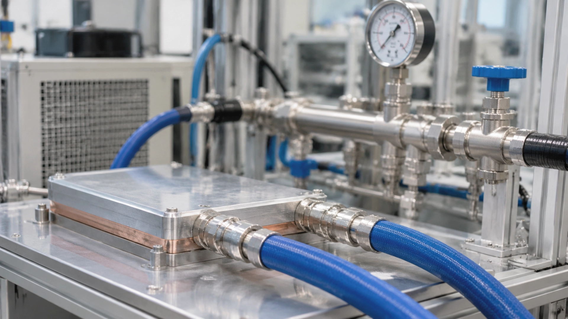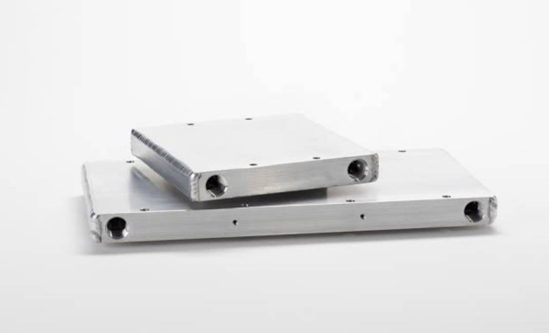
A cold plate is a liquid-cooled heat exchanger that removes heat from a component through a metal surface and transfers it to a circulating coolant. It is commonly used when air cooling cannot keep temperatures within the required limits, particularly in systems with high heat loads, concentrated hot spots, or limited installation space.
A cold plate does not generate cooling by itself. It provides a controlled path for heat to move from the component into the coolant, while the rest of the liquid cooling loop carries that heat away. This guide explains what cold plates are, how they work, how aluminum and copper compare, where they are used, when liquid cooling makes more sense than air, and what to check before integrating a cold plate into a system. It focuses on the engineering fundamentals rather than specific products or supplier selection.
1. What Is a Cold Plate?
A cold plate is a metal plate with internal channels that allow coolant to flow through it. The component being cooled is mounted against one side of the plate. Heat passes through the contact interface and the metal base into the coolant inside the channels.
Definition and Core Components
A typical cold plate has five main parts:
- Metal base: Provides the mounting surface and conducts heat away from the component. Aluminum and copper are common choices.
- Internal flow channels: Direct coolant through the plate. Their size, shape, and layout affect heat transfer and pressure drop.
- Inlet and outlet ports: Connect the cold plate to the external cooling circuit.
- Mounting interface: Holds the plate against the component and helps maintain consistent contact pressure.
- Thermal interface material (TIM): Fills small gaps between the component and the plate, reducing contact resistance caused by surface roughness and unevenness.
Cold plate performance depends on the complete thermal path. A well-designed internal channel cannot compensate for poor contact between the component and the plate.
Where It Sits in a Liquid Cooling Loop
The cold plate is one part of a larger cooling system. A typical loop includes the cold plate, piping and quick connects, a pump, a CDU or heat exchanger, and a return line. The cold plate absorbs heat from the component; the pump maintains coolant circulation; the CDU or heat exchanger rejects that heat to a facility water loop or another heat-rejection system; and the return line carries cooled coolant back to the cold plate.
The exact component order depends on the system architecture. The pump may be integrated into a CDU or installed elsewhere in the loop. The operating principle remains the same: coolant absorbs heat at the cold plate and carries it to a heat-rejection component.
Cold Plate vs. Heat Sink
A heat sink transfers heat to surrounding air, usually with the help of fins and airflow. A cold plate transfers heat to liquid flowing through internal channels. The main difference is the cooling medium: air for a heat sink, liquid for a cold plate. That difference is why cold plates can handle higher heat flux and more compact installations, while heat sinks remain simpler and often sufficient for lower-power components.
2. How Does a Cold Plate Work?
A cold plate removes heat through two main processes: conduction through solid materials and convection between the channel walls and moving coolant. Actual performance depends on the contact interface, plate geometry, coolant conditions, and flow rate.
Heat Transfer Path
Heat moves through the system in a defined sequence: the component generates heat; the heat crosses the TIM; the metal base conducts it away from the mounting surface; it passes through the channel wall; and the flowing coolant absorbs it and carries it out of the cold plate.
Conduction moves heat through the component interface and metal plate. Convection transfers heat from the channel walls into the flowing coolant. Both are necessary for the cold plate to remove heat effectively.
Coolant Flow and the Wider Loop
As coolant passes through the internal channels, it absorbs heat and its temperature rises. The heated coolant then flows to a CDU or heat exchanger, where the heat is transferred to another cooling circuit or heat-rejection system. The cooled fluid returns to the cold plate, and the cycle repeats.
Three operating conditions affect this process:
- Flow rate: Determines how much coolant passes through the plate over a given period. It affects coolant temperature rise and convective heat transfer.
- Pressure drop: Represents the pressure loss as coolant moves through the channels, ports, and other restrictions. The pump must provide enough pressure to maintain the required flow.
- Coolant properties: Thermal conductivity, specific heat capacity, viscosity, and compatibility with the plate materials all affect system performance.
Increasing flow rate may improve heat transfer, but it also tends to increase pressure drop and pumping demand. The best operating point depends on the channel design and the limits of the complete cooling loop.
Thermal Resistance, Flow Rate, and Pressure Drop
Thermal resistance describes how difficult it is for heat to move from one point to another. A lower thermal resistance means less temperature difference is needed to transfer the same amount of heat. A simplified relationship is:
Thermal resistance = Temperature difference ÷ Heat load
For a cold plate, the overall thermal path includes contact resistance, conduction through the plate, and heat transfer to the coolant. Measuring only the metal’s thermal conductivity does not tell you how the complete assembly will perform.
Pressure drop is a separate but related design constraint. Narrow channels and complex flow paths can increase coolant-side heat transfer, but they may also restrict flow. If the pressure drop exceeds the pump’s available capacity, the system may not deliver the required coolant flow.
Cold plate design therefore involves balancing thermal resistance, pressure drop, flow rate, and pumping power rather than optimizing one parameter in isolation.
3. Aluminum vs. Copper: Materials and Construction
Aluminum is often selected when weight and cost matter. Copper is considered when its higher thermal conductivity can help manage heat spreading or reduce temperature differences across the plate. Neither material is automatically the better choice for every application.
Aluminum vs. Copper
| Factor | Aluminum | Copper |
|---|---|---|
| Thermal conductivity | Lower than copper | Higher than aluminum |
| Weight | Lighter | Heavier |
| Material cost | Generally lower | Generally higher |
| Heat spreading | May require more careful base and channel design | Can spread heat more effectively across the plate |
| Typical considerations | Useful for weight-sensitive and cost-sensitive designs | Useful where higher thermal conductivity is important |
Material selection must also account for coolant chemistry and corrosion. Corrosion resistance cannot be judged from the base metal alone. Coolant composition, water quality, galvanic contact with other metals, surface treatments, and operating conditions all matter.
Common Construction Methods
Cold plates can be manufactured using different methods. The suitable process depends on channel geometry, heat load, production volume, and sealing requirements.
- Machined cold plates: Channels are cut into a metal plate and closed with a cover. Machining allows precise control of channel dimensions and port locations.
- Stamped cold plates: Formed metal sheets create the flow passages. Stamping can be suitable for repeat production of relatively thin structures.
- Tube-based cold plates: Tubes are embedded in or attached to a metal base. The tube carries coolant while the base provides the component mounting surface.
- Brazed cold plates: Metal sections are joined through brazing to create sealed internal passages. The process can produce compact assemblies with integrated channels.
- Welded cold plates: Covers or channel sections are joined by welding. Joint quality and distortion control are important for leak prevention and dimensional accuracy.
- Additively manufactured cold plates: Internal passages are formed during the printing process. This allows complex channel geometries, although material, surface finish, inspection, and production cost must be considered.
How to Choose Between Aluminum and Copper
Start with the thermal and mechanical requirements, then compare material cost and manufacturing constraints. Key factors include:
- Heat load and temperature uniformity: Consider whether the component produces concentrated hot spots or distributes heat across a larger surface. Copper’s higher conductivity may help spread concentrated heat.
- Weight limits: Aluminum is generally preferable when the cooling assembly must remain light, such as in mobile or vehicle-mounted equipment.
- Coolant compatibility: Check the coolant against every wetted material, including the plate, fittings, seals, and other loop components.
- Manufacturing complexity: Deep channels, thin walls, complex internal passages, and sealing features may affect which production process is practical.
- Cost: Compare the total assembly cost, not just the raw material price. Machining time, joining, finishing, inspection, and scrap can change the final cost.
- Installation constraints: Check the available footprint, thickness, mounting points, port locations, and allowable weight.
The right material is the one that meets the required thermal performance while remaining compatible with the coolant, manufacturing process, and installation environment.
4. Cold Plate Types and Internal Channel Architectures
Material and manufacturing route should be selected together with the internal channel architecture. The best type depends on heat flux, required thermal resistance, coolant pressure, production volume, sealing requirements, and available space. A cost-sensitive industrial plate and a high-heat-flux processor plate may share the same material but need very different channel geometry and joining methods.
Tubed Cold Plates
A tubed cold plate uses a tube as the coolant passage, with the tube attached to or embedded in a conductive body that provides the thermal contact surface. The tube carries coolant through a defined route while the surrounding body spreads heat toward the tube wall. This architecture suits low-to-moderate power applications where cost, straightforward construction, and simple routing matter. Thermal performance depends on tube material, tube-to-body contact, available heat-transfer area, and coolant flow. The retention method must maintain contact and mechanical stability under operating conditions.
Machined Channel Cold Plates with Sealed Cover
A machined-channel cold plate cuts coolant passages directly into a metal base, usually by CNC milling, then seals the open channels with a cover. This allows specific inlet and outlet locations, flow paths, mounting features, and passage dimensions. The cover-joining method affects pressure capability, cost, distortion, and long-term sealing reliability. FSW is suitable when a robust aluminum joint and reliable sealing are priorities, including demanding pressure requirements. Vacuum brazing is useful when fins, covers, or multiple contact areas need broad metallurgical bonding. Channel depth, wall thickness, tool access, burr removal, sealing-land geometry, and post-joining machining allowances all belong on the drawing.
Skived Fin Cold Plates
A skived fin cold plate lifts thin fins from a solid metal base without cutting them completely away. The fins and base remain one continuous piece of metal, avoiding the interface resistance of separately attached fins. Skiving can produce high fin density and substantial surface area in a compact structure, making it useful for high-heat-flux applications. Because the fins are formed from the base material, there is no separate fin-to-base brazed joint. Fin height, thickness, spacing, material properties, and coolant flow still determine performance; high fin density alone does not guarantee better cooling if pressure drop or flow distribution becomes poor.
Vacuum Brazed Cold Plates
Vacuum brazed cold plates use a controlled brazing process to join fins, covers, or other metal features into a sealed assembly. The process can create broad metallurgical bonds across complex contact areas and produce internal structures that would be difficult to machine as a single piece. However, the brazing thermal cycle can move the contact face. Post-braze machining stock and a final leak test after the finish cut are not optional when tight contact-surface control and verified sealing are required. The manufacturing plan should account for distortion, provide finishing allowances, and define inspection criteria for the completed assembly.
FSW (Friction Stir Welding) Cold Plates
Friction stir welding joins metal components through frictional heating and mechanical stirring rather than fusion welding. In aluminum cold plate manufacturing, FSW can create a solid-state joint between a machined base and a cover, supporting a sealed internal coolant structure. FSW heats the aluminum locally; the face will move. Design with post-weld machining stock where geometry and distortion allowance require it, finish the contact surface after joining, and leak-test after the final cut. The actual allowance should be confirmed through material selection, joint geometry, process development, and dimensional validation rather than applied unconditionally to every design.
Additive Manufactured / Conformal Cooling Cold Plates
Additive manufacturing can produce internal passages and conformal cooling geometries that are difficult to create with conventional machining or joining. It may be useful when highly customized flow paths or complex three-dimensional structures are required. Material availability, internal surface quality, powder removal, inspection access, cost, and production repeatability must be evaluated for the specific application. Conventional skiving, CNC machining, FSW, and vacuum brazing remain relevant where their established routes meet the thermal, mechanical, and production targets.
5. Coolants, Compatibility, and Channel Cleanliness
Coolant choice affects more than heat transport. Chemistry, electrical properties, viscosity, additives, and interaction with wetted materials determine corrosion risk, pressure drop, maintenance requirements, and long-term channel cleanliness. Water and water-glycol mixtures are common; deionized water and dielectric fluids may be used in specific system designs. No coolant should be selected on thermal conductivity alone without checking compatibility with the complete wetted-material system.
The following table is a preliminary screening guide, not a universal compatibility certification. Actual compatibility depends on alloy grade, coolant formulation, inhibitor package, temperature, electrical conditions, seals, coatings, and operating duration.
| Wetted material | Water | Glycol-water mixture | Deionized water | Dielectric fluids: PAO, silicone, fluorinated fluids |
|---|---|---|---|---|
| Copper | Potentially suitable with controlled chemistry and appropriate corrosion management. | Depends on the glycol formulation, inhibitors, temperature, and mixed-metal loop. | Requires monitoring because water chemistry and conductivity can change during operation. | Depends on the specific fluid, seals, coatings, and component materials. |
| Aluminum | Requires control of pH, dissolved species, and corrosion inhibitors where applicable. | Requires a compatible inhibitor package and careful control in mixed-metal systems. | Requires a validated chemistry and monitoring plan; deionized does not mean corrosion-proof. | Requires fluid-specific compatibility testing, including seals and surface treatments. |
| Stainless steel | Often suitable, depending on grade, water chemistry, and chloride exposure. | Depends on the fluid formulation, temperature, and other loop materials. | Requires consideration of grade, operating chemistry, and system contamination. | Depends on fluid formulation, seals, and the full wetted-material assembly. |
Glycol can provide freeze protection, but it does not automatically eliminate corrosion risk. In a mixed copper-aluminum loop, dissimilar-metal contact, coolant chemistry, inhibitor depletion, and electrical conditions can contribute to galvanic corrosion. The complete loop should be designed around compatible materials and a coolant formulated for the intended service.
Filtration is equally important. Particles and residues can accumulate in narrow channels, reducing flow area and changing pressure drop. A filtration specification should reflect the smallest relevant channel feature, the coolant cleanliness requirement, and contamination risks introduced during manufacturing, assembly, and maintenance.
Early Warning Signs of Galvanic Corrosion — What to Monitor Before the Leak
Galvanic corrosion can progress before an obvious external leak appears. Monitoring coolant condition and hydraulic performance can help identify developing problems, although no single indicator proves galvanic corrosion is occurring. A useful monitoring plan establishes a baseline after commissioning and tracks changes under comparable operating conditions.
- Rising coolant electrical conductivity: An increase may indicate dissolved ionic species or contamination. Interpret the trend alongside coolant type, temperature, and the established baseline.
- pH drift: A sustained shift away from the coolant supplier’s specified range may indicate chemical degradation, contamination, or changes in inhibitor performance.
- White or blue-green gel-like deposits: Deposits may indicate corrosion products or coolant degradation, but composition should be confirmed before drawing a conclusion.
- A gradually increasing inlet-to-outlet temperature difference: Under comparable heat loads and flow conditions, a changing temperature difference may indicate reduced flow, fouling, or a change in heat-transfer performance.
- Aluminum ion concentration above 1 ppm: This can be treated as a screening trigger for investigation when appropriate to the coolant chemistry and measurement method. It is not a universal failure threshold; confirm the result and compare it with the applicable coolant specification and baseline.
- An unexplained rise in pressure drop: A rising pressure drop at comparable flow conditions may indicate channel restriction, deposits, or other hydraulic changes. Check instrumentation and operating conditions before attributing the change to corrosion.
Surface treatment such as anodizing slows galvanic attack, but it cannot replace loop-level monitoring — cold plate life is co-determined by plate chemistry and loop chemistry. Anodizing and sandblasting may be available as manufacturing surface treatments, but their suitability depends on the application. Anodizing must be specified with attention to coating integrity and areas requiring electrical, thermal, or sealing contact.
Channel Cleanliness Is a Manufacturing CTQ, Not a System Afterthought
Microchannel blockage can originate from manufacturing residues as well as coolant degradation products. Metal chips, burrs, brazing flux residues, and particles introduced during assembly can remain inside a passage if cleaning and verification are inadequate. Once the system is operating, such contaminants may migrate, accumulate in narrow sections, obstruct local flow, or change pressure drop. External dust is not the only concern, and it is often not the primary source of contamination inside a sealed liquid-cooling circuit.
Channel cleanliness should be defined as a critical-to-quality (CTQ) requirement and controlled through manufacturing. After CNC machining, the process should address burr removal, chip evacuation, flushing, drying, and cleanliness verification. The inspection method and acceptance criteria should be appropriate to the internal geometry and intended coolant. For brazed structures, the cleaning and verification plan should also account for the joining process and any residues that may remain after thermal processing.
Filtration should be selected in relation to the smallest relevant channel feature and the system’s contamination tolerance. A filtration range of 25–50 μm can serve as an initial reference for some microchannel applications, but it is not a universal specification. The appropriate filter rating depends on minimum passage dimensions, particle-size distribution, allowable pressure drop, filter capacity, and the risk of particles obstructing critical features.
Jindu connects CNC finishing and post-processing with explicit cleanliness requirements — deburring, flushing, drying, and verification — as part of the manufacturing plan. A drawing that specifies only channel dimensions without defining cleanliness leaves a critical requirement open to interpretation.
6. Where Cold Plates Are Used
Cold plates are used when heat must be removed from a specific component or surface and air cooling cannot meet the temperature, space, or operating requirements. Common applications include data centers, power electronics, electric vehicles, and specialized equipment.
Data Centers and AI Infrastructure
High-performance CPUs, GPUs, and AI accelerators can generate substantial heat within a small area. Air cooling becomes harder to manage as rack power density increases and more heat must be removed from individual processors.
A cold plate mounted directly against a processor or accelerator transfers heat into a data center liquid cooling loop. This allows heat to be collected close to its source instead of relying entirely on airflow through the server.
Power Electronics
Power converters, inverters, rectifiers, and semiconductor modules generate heat during switching and power conversion. Their operating temperature affects efficiency, reliability, and service life.
Cold plates can be mounted beneath power modules or against their designated cooling surfaces. Channel layout and contact conditions must account for the component’s heat distribution, not just its total power rating.
EV and Battery Systems
Electric vehicles use liquid cooling in several parts of the powertrain. Cold plates or liquid-cooled plates can remove heat from battery modules, inverters, and other power electronics.
For battery systems, temperature uniformity matters alongside heat removal. Uneven temperatures between cells can affect performance and aging. The cooling plate must therefore be designed around the module layout, contact surfaces, coolant distribution, and operating conditions.
Other Applications
Cold plates are also used in medical equipment such as imaging and diagnostic systems, laser systems where stable temperature control supports operating conditions, and aerospace or defense electronics where space, weight, and heat dissipation must be considered together.
In each application, the cold plate must match the component’s heat load, mounting interface, coolant requirements, and operating environment.
7. Cold Plates vs. Air Cooling
Air cooling remains the simpler default when a heat sink and fan can keep the component within its temperature limit inside the available enclosure. A cold plate becomes worth evaluating when heat is concentrated, airflow is restricted, packaging is tight, or an air-cooled heat sink would need excessive volume, fan speed, or noise to meet the same target. The trade-off is system-level: a cold plate adds a coolant loop, pump, heat exchanger, sealing, and maintenance requirements, but it can move heat away from the source more flexibly. The right choice is not liquid by default; it is the architecture that meets the thermal, hydraulic, acoustic, and packaging limits at acceptable complexity. For a detailed decision framework, see our liquid cooling vs. air cooling comparison for high-power electronics.
8. How to Specify a Cold Plate: A Practical Checklist
A useful cold plate specification connects thermal requirements to mechanical interfaces, hydraulic limits, manufacturing processes, and quality-control criteria. The checklist below helps engineering teams and buyers define requirements before requesting quotations or approving a production drawing.
-
Heat Load and Heat Flux
Define the total heat load and, where possible, the heat distribution over the contact area. Total heat load establishes how much energy the coolant must carry away; heat flux indicates how concentrated the thermal input is. These values influence base thickness, fin density, channel placement, and required contact area.
-
Allowed Thermal Resistance
Specify the maximum permitted thermal resistance or the required component temperature under defined operating conditions. This requirement helps determine material selection, base geometry, channel architecture, and heat-transfer surface area. Evaluate it together with coolant inlet temperature, flow rate, heat load, and interface conditions.
-
Pressure Drop Budget
Define the allowable pressure drop across the cold plate at the intended coolant flow rate. Channel width, channel height, pin-fin spacing, passage length, and flow distribution all influence hydraulic resistance. A design may meet the thermal target at one flow rate but become unsuitable if the pump cannot provide the required pressure.
-
Coolant and Loop Material
Identify the coolant formulation, operating temperature range, expected flow conditions, wetted materials, and any required corrosion inhibitors. Copper, aluminum, stainless steel, coatings, seals, and fittings must be evaluated as part of the same loop. A coolant suitable for one material combination may not be appropriate for another. Review the coolant compatibility section and confirm the selected chemistry with the coolant supplier.
-
Flatness, Conformity, and Mounting Pressure
Specify the contact-surface geometry, relevant datums, mounting method, clamping force, and TIM requirements. A perfectly flat cold plate may underperform on a package whose integrated heat spreader carries a slight curvature; conformity to the target profile can matter more than absolute flatness. Specify the interface, not just the plate. The required surface geometry should be based on the actual component package and mounting conditions rather than an assumption that every mating surface should be perfectly planar.
Flatness must also remain sufficiently stable over the intended thermal and mechanical duty cycle. A plate that meets its initial tolerance but changes shape under repeated heating and cooling may accelerate TIM pump-out and degrade contact over time. The specification should distinguish initial flatness from the required dimensional stability after relevant processing and operating conditions.
-
Leak Integrity Requirement
Specify the coolant boundary, operating pressure, test method, acceptance criteria, and any required test documentation. The sealing method may influence the choice between FSW, vacuum brazing, soldering, or another suitable joining approach. Test conditions must be appropriate to the design and the customer’s acceptance requirements. Jindu performs 100% air-tightness testing before shipment, making final leak verification a defined part of manufacturing and quality control rather than an assumption based only on the joining method.
-
Drawing CTQs
Identify critical-to-quality characteristics directly on the drawing or in the accompanying specification. Datums must correspond to the actual clamping and measurement references; sealing surfaces should include appropriate surface-roughness requirements; channels should have defined cleanliness, flushing, and drying requirements; and post-joining flatness requirements should allow for finish machining after the joining process. Most cold plate failures are not thermal-math problems — they come from CTQs that were never defined on the drawing.
Manufacturing requirements should also state which dimensions are critical, how they will be measured, and what constitutes acceptance. If brazing or FSW can distort the contact face, the process plan should define the required machining allowance and the point at which final dimensional inspection and leak testing occur.
-
Prototype-to-Production Path
Define the expected prototype quantity, sample turnaround requirements, production volumes, inspection requirements, and anticipated demand changes. A prototype that demonstrates thermal performance is not automatically proof of stable mass-production capability. Tooling, process controls, material sourcing, cleaning procedures, joining parameters, and final inspection must be suitable for the intended production volume. Jindu supports development from prototyping to mass production, with stated annual part capacity above 50,000 units and IATF 16949 quality-system capability, subject to the applicable product and certification scope.
Once these requirements are documented, engineering teams can compare manufacturing proposals on a consistent basis. To discuss drawings, operating conditions, or production requirements, request a quote or contact the engineering team.
9. Common Misconceptions About Cold Plates
- A cold plate is a complete cooling system. It transfers heat into coolant, but a pump, coolant circuit, and heat-rejection component are still required.
- Copper is always better than aluminum. Copper conducts heat better, but it is heavier and generally more expensive. Aluminum may be the better overall choice when weight, cost, and required thermal performance are considered together.
- Installing a cold plate automatically solves overheating. Poor contact, insufficient flow, excessive pressure drop, high coolant inlet temperature, or inadequate heat rejection elsewhere in the loop can still cause overheating.
- Higher coolant flow always means better cooling. Higher flow can improve convective heat transfer, but it also increases pressure drop and pumping demand. The goal is a flow rate that meets the thermal requirement without exceeding the hydraulic limits.
10. Frequently Asked Questions
Cold Plate vs. Heat Sink — What’s the Difference?
A conventional heat sink transfers heat into the surrounding air, usually through fins and natural or forced airflow. A liquid cold plate transfers heat into a coolant flowing through internal passages, which carries the energy to a remote heat exchanger. A cold plate can be advantageous when heat flux is high, space is limited, or the system needs controlled heat removal. The best choice depends on the thermal load, operating environment, available airflow, and overall system design.
How Much Pressure Drop Is Acceptable for a Cold Plate?
There is no single acceptable pressure-drop value for every cold plate. The limit depends on the available pump head, required flow rate, pressure losses of the rest of the loop, and the thermal performance target. A cold plate with dense fins or narrow passages may improve heat transfer while increasing hydraulic resistance. Specify pressure drop at a defined coolant, temperature, and flow rate, then evaluate the result alongside the complete system’s pumping capacity.
Can a Cold Plate Be Repaired After a Leak?
Repair feasibility depends on leak location, base material, joining method, coolant contamination, operating pressure, and required reliability. Some external fittings or accessible joints may be serviceable, while a leak through an internal passage or a sealed brazed or welded assembly may require replacement. Any proposed repair must be assessed for material compatibility, structural integrity, dimensional changes, and repeat leak-test results. For safety-critical or high-reliability applications, replacement may be more appropriate than an unqualified repair.
Is Copper Always Better Than Aluminum for Cold Plates?
No. Copper generally offers higher thermal conductivity, but it is heavier and may have higher material and manufacturing costs. Aluminum provides a useful balance of weight, thermal performance, machinability, and compatibility with processes such as skiving and FSW. The best choice depends on heat flux, allowable thermal resistance, coolant chemistry, joining requirements, and cost. Material selection should be made together with channel architecture and manufacturing process.
What Filtration Level Does a Microchannel Cold Plate Need?
The required filtration level depends on the smallest channel feature, particle contamination risk, coolant condition, and allowable pressure drop across the filter. A 25–50 μm filter rating may be an initial reference for some microchannel systems, but it should not be applied universally. The specification should account for particle size and shape, filter capacity, and the possibility of contamination introduced during manufacturing or maintenance. Channel cleanliness, flushing, drying, and verification are also necessary because filtration alone cannot remove residues already trapped inside a plate.
How Is a Cold Plate Leak-Tested?
Cold plates may be checked using a suitable pressure-decay, pressure-hold, or tracer-gas method, depending on the design, sensitivity requirement, and acceptance specification. The test pressure, duration, medium, and allowable leakage must be defined for the application. Testing should take place after final machining and any operation that could affect the coolant boundary. Jindu performs 100% air-tightness testing before shipment according to applicable product requirements; the specific method and acceptance criteria should be confirmed for each project.
11. Key Takeaways
- A cold plate transfers heat to liquid coolant. It is a heat exchanger within a larger liquid cooling loop, not a standalone cooling system.
- Thermal performance depends on the complete heat path. Component contact, TIM, plate material, channel geometry, and coolant flow all affect the result.
- Aluminum and copper serve different design priorities. Copper offers higher thermal conductivity, while aluminum is lighter and generally less expensive.
- Cold plates are useful when air cooling reaches its limits. High heat flux, restricted airflow, and compact equipment are common reasons to consider liquid cooling.
- Thermal and hydraulic requirements must be evaluated together. Heat removal, pressure drop, coolant compatibility, and installation constraints all influence whether a design will work.
When evaluating a cold plate, start with three questions: How much heat must be removed? What pressure drop can the cooling loop support? What installation constraints must the design meet?
Why Choose Jindu for Your Cold Plate Manufacturing
Jindu manufactures the component where conduction meets convection — using skiving, friction stir welding (FSW), vacuum brazing, soldering, and precision CNC machining, with 100% air-tightness validation before shipment. These manufacturing processes support different cold plate geometries, sealing requirements, and thermal design objectives. For product-level details and manufacturing options, explore our liquid cold plate manufacturing capabilities.
If you are developing a cold plate for electronics, power systems, data centers, or other demanding thermal applications, start with the component’s heat load, coolant conditions, interface drawing, and pressure requirements. Visit our liquid cold plate manufacturing page or contact our engineering team to discuss your design and request a quote.