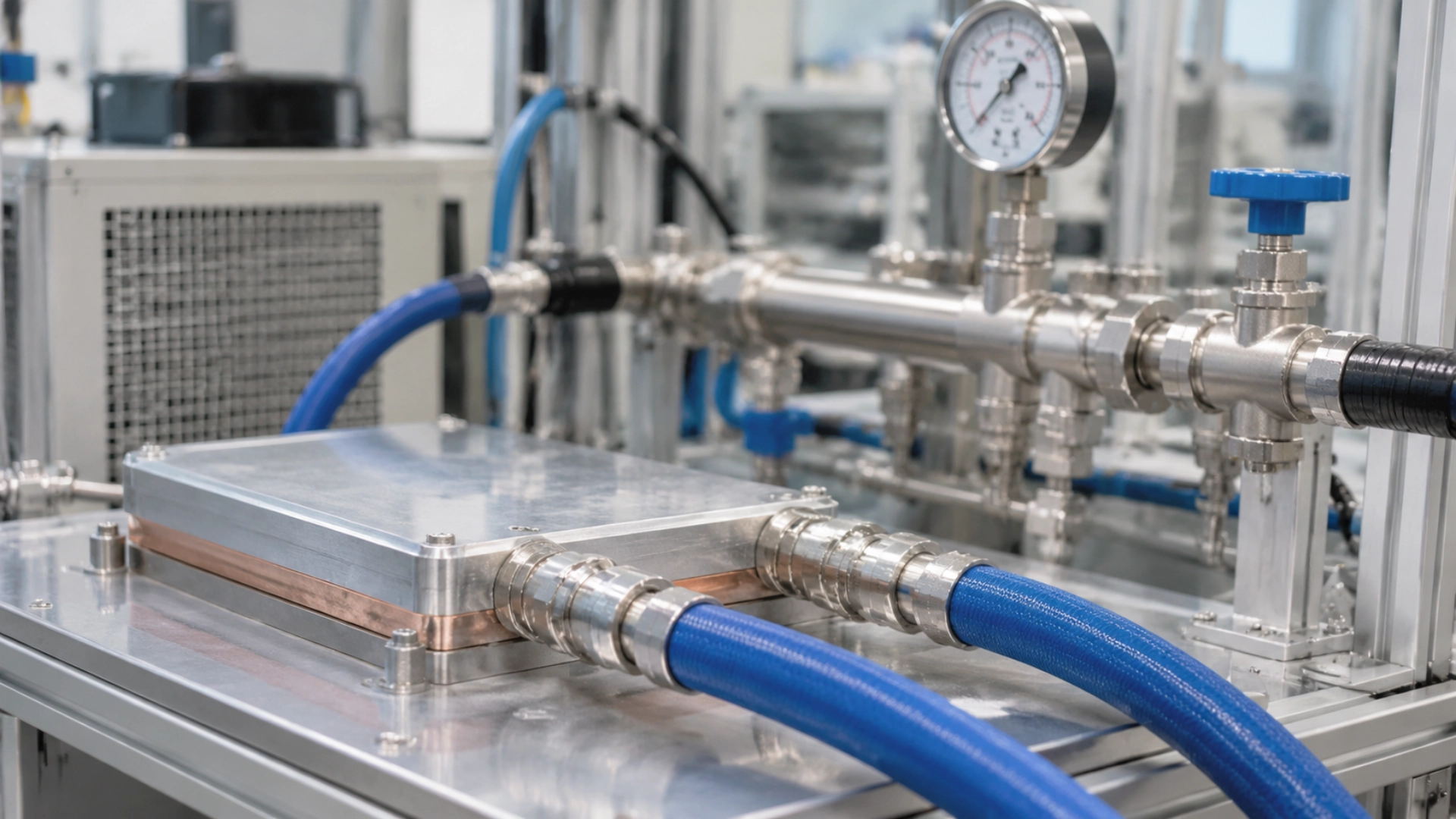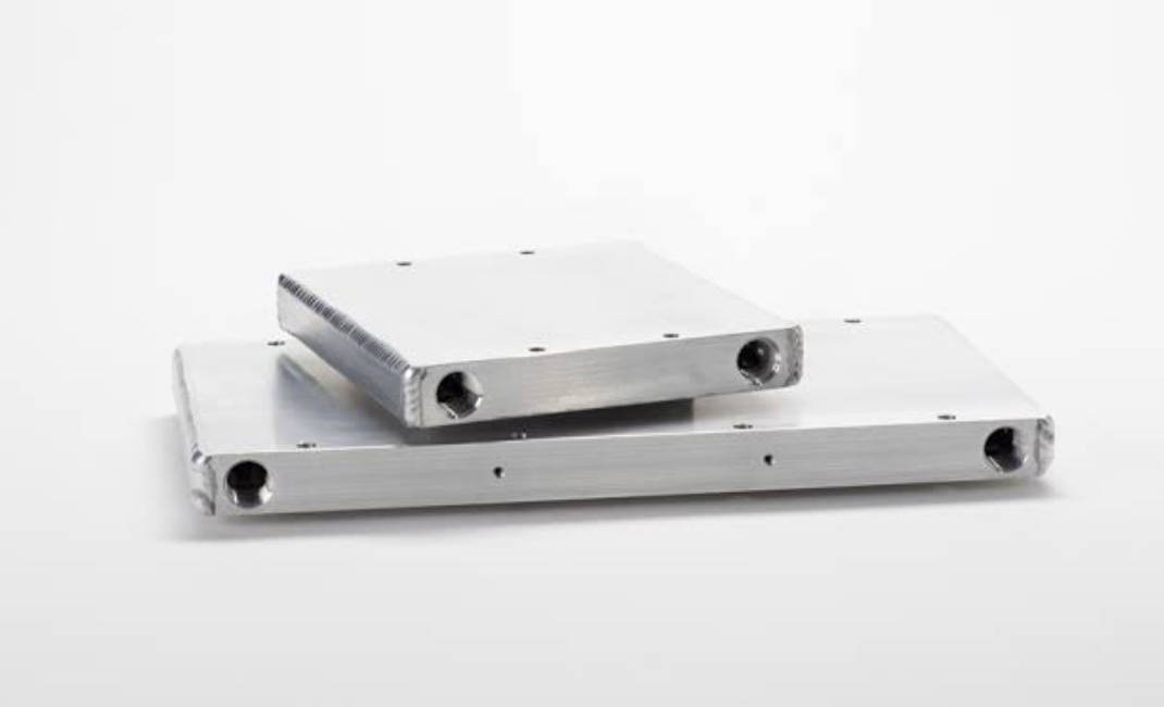
For a liquid cold plate, a successful leak test must prove more than the absence of visible leakage. It must show whether the component meets a defined leak-rate limit under specified test conditions.
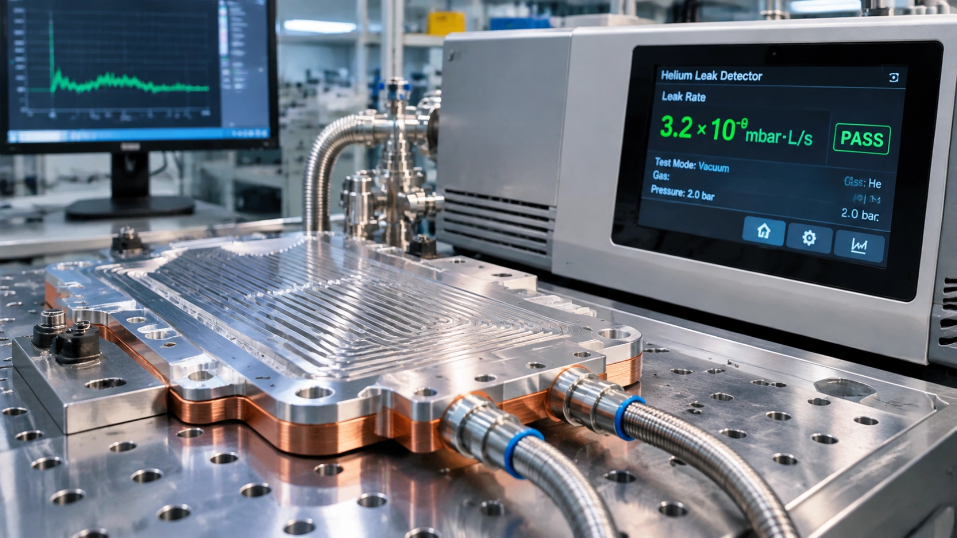
Helium leak detection is particularly useful for cold plates with microchannels, brazed joints, welded seams, and complex manifolds. It can identify leakage paths that pressure decay or bubble testing may miss.
The key decisions are straightforward: set an acceptable leak rate, choose the right testing method, and verify that the test report contains actual measurement data. This guide explains how to make those decisions and what to check before approving a cold plate for production.
Why Leak Rate Is the Only Metric That Matters
A leak test result is only useful when it tells you how much gas escapes. A statement such as “Passed leak test” does not tell an engineer whether the cold plate meets the application’s sealing requirements.
Leak rate measures the amount of gas passing through a leak per unit of time. It is commonly expressed in mbar·L/s or atm·cc/s. The smaller the value, the lower the measured gas leakage under the specified test conditions.
Consider a cold plate with an internal brazed channel structure. A conventional air test may show no visible leakage, yet a helium detector may identify a much smaller leakage path at a joint. Both tests can produce a pass/fail result, but they do not provide the same level of evidence.
How Different Testing Methods Compare
| Testing Method | Indicative Detection Range | Typical Use | Main Limitation |
|---|---|---|---|
| Bubble testing | Approximately 10-3 mbar·L/s and above, depending on conditions | Finding visible leaks | Cannot reliably quantify micro-leaks |
| Pressure decay testing | Approximately 10-3 to 10-4 mbar·L/s in suitable systems | Production screening | Sensitive to temperature and test volume |
| Helium leak detection | Approximately 10-6 to 10-9 mbar·L/s, depending on equipment and configuration | Micro-leak detection and quantification | Requires specialized equipment and controlled procedures |
Note: These are indicative equipment and method capabilities, not universal acceptance limits. Actual detection performance depends on the detector, test setup, component geometry, background helium, and inspection procedure. Bubble testing does not provide a reliable quantitative leak-rate measurement.
For an EV battery cooling system, a leak may allow coolant to reach nearby electrical connections. In a data center cooling system, leakage from a manifold or internal channel can damage adjacent equipment. The acceptable leak rate must reflect these risks, along with the coolant, operating pressure, and system design.
Do not select an acceptance limit simply because a supplier’s equipment can measure it. Define the required value in the product specification first, then verify that the testing process can reliably detect it.
mbar·L/s vs. atm·cc/s: A Quick Conversion Guide
Helium leak test reports commonly use mbar·L/s and atm·cc/s. Both measure gas throughput, but their numerical values are not exactly identical.
The conversion is:
1 atm·cc/s = 1.01325 mbar·L/s
For most engineering comparisons, the difference is small. However, buyers should use the same unit when comparing supplier reports.
| mbar·L/s | Approximate atm·cc/s |
|---|---|
| 10-3 | 9.87 × 10⁻⁴ |
| 10-4 | 9.87 × 10⁻⁵ |
| 10-6 | 9.87 × 10⁻⁷ |
| 10-8 | 9.87 × 10⁻⁹ |
| 10-9 | 9.87 × 10⁻¹⁰ |
One more detail matters: the reported leak rate must be interpreted in the context of the test gas, pressure, and measurement method. Two numbers with the same unit are not necessarily comparable if the test conditions differ.
The 3 Leak Testing Methods: Helium vs. Pressure Decay vs. Bubble
The choice of leak testing method comes down to two questions: how small a leak must be detected, and how many parts need to be tested per shift.
Bubble testing is useful for finding visible leakage. Pressure decay works well for automated production screening when its detection capability is sufficient. Helium testing is the preferred option when a cold plate has a strict, measurable micro-leak requirement.
Bubble Test: Fast Localization, Limited Micro-Leak Sensitivity
Bubble testing is a simple way to locate relatively large leaks. The cold plate is pressurized with air or another suitable gas and submerged in water, or a leak detection solution is applied to the suspected area.
Gas escaping through a defect produces visible bubbles.
Operators commonly use this method to inspect:
- Visible brazed seams and welded joints.
- Manifold connections and external fittings.
- Port interfaces and sealing surfaces.
- Obvious cracks or damaged areas.
Its main advantage is that it shows where gas is escaping. An operator can often identify a defective connection without connecting the component to a specialized detector.
The limitation is sensitivity. A very small leak may produce bubbles too slowly to be noticed during the inspection period. Bubble size and formation rate also do not provide a dependable measurement of the actual leak rate.
For that reason, bubble testing is useful for preliminary inspection and gross leak detection, but it should not be the sole acceptance method when a cold plate must meet a strict micro-leak specification.
Best suited for: Visible leak localization, preliminary checks, and relatively large leakage paths.
Pressure Decay Test: Great for Production Lines, but Watch for Temperature Drift
Pressure decay testing measures the pressure loss inside a sealed cold plate over a defined period. It is commonly used on automated production lines because the equipment can test parts without helium.
The process follows six steps:
- Connect the cold plate to a sealed test fixture.
- Fill the internal passages with compressed air or nitrogen.
- Raise the pressure to the specified test value.
- Allow the component and fixture to stabilize.
- Isolate the gas supply and record the pressure change.
- Compare the result with the permitted pressure loss.
If pressure falls beyond the acceptance threshold, the component is flagged for further inspection.
This method is practical when a manufacturer needs to screen large batches of cold plates. It is easy to automate, has relatively low consumable costs, and can provide short inspection cycles once the process is established.
But pressure decay has a measurement problem: pressure can change even when there is no leak.
For example, compressed air heats up during filling. If the test begins before the air and component reach thermal equilibrium, the pressure may fall as the system cools. The tester could mistake this temperature-related change for a leak.
Internal volume creates another limitation. The same pressure drop can correspond to different gas leakage rates in cold plates with different internal volumes.
To obtain consistent results, manufacturers need to control:
- Initial gas temperature and component temperature.
- Stabilization time before measurement.
- Internal volume and fixture dead volume.
- Test pressure and measurement duration.
- Temperature changes during the inspection cycle.
Best suited for: High-volume production screening when the validated detection threshold meets the product specification.
Helium Leak Detection: The Gold Standard for Micro-Channel Cold Plates
Helium leak detection uses a mass spectrometer to identify helium escaping through a leakage path. It is particularly useful when the leak is too small for a conventional pressure decay or bubble test to detect reliably.
Helium is suitable as a tracer gas because it is chemically inert, non-flammable, and naturally present at a low concentration in the atmosphere. This makes it possible for a properly configured detector to distinguish the helium signal from the background.
For a cold plate, the detector can help identify leakage around:
- Internal microchannel walls.
- vacuum-brazed joints between metal plates.
- Friction stir welded seams.
- Deep-drilled passages and plugged openings.
- Manifold-to-plate connections.
These locations are difficult to inspect visually. A small defect inside a brazed channel may not produce an obvious external sign, but it can still allow coolant to escape under operating conditions.
Helium testing provides a numerical leak-rate result that can be compared with a defined acceptance limit. This makes it suitable for products where leakage performance must be documented rather than judged by appearance alone.
It does require more specialized equipment and tighter process control. The test fixture, helium supply, background level, calibration, and measurement sequence all affect the result.
Best suited for: Microchannel cold plates, critical brazed or welded assemblies, and cooling systems with strict leakage requirements.
Vacuum vs. Sniffer: Choosing the Right Helium Method for Cold Plates
Helium leak detection can be performed using a vacuum chamber or a sniffer probe. The main difference is what the test is designed to establish.
A vacuum chamber measures helium entering an evacuated enclosure. A sniffer probe samples helium escaping from a pressurized component. The first is generally better for total leak-rate measurement; the second is better for locating a suspected leak.
Vacuum Chamber Method: Best for Total Leak Rate Quantification
In a vacuum chamber test, helium is introduced into the cold plate’s internal passages while the component is placed inside a sealed chamber connected to a helium mass spectrometer leak detector.
The chamber is evacuated. If helium escapes through a defect in the cold plate, it enters the chamber and is measured by the detector.
A typical inspection involves:
- Connect the cold plate to the helium charging fixture.
- Fill the internal passages with helium at the specified pressure.
- Seal the connections and place the component inside the chamber.
- Evacuate the chamber to the required test conditions.
- Measure the helium signal.
- Compare the measured leak rate with the specified maximum.
The result can provide a quantitative measurement of total leakage under the defined test conditions. This is useful when a buyer needs a numerical result for final inspection or production release.
For large cold plates, however, chamber dimensions and fixture design matter. The manufacturer must also consider the component’s internal volume, port arrangement, pressure rating, and evacuation requirements.
Choose vacuum chamber testing when: The specification requires a documented total helium leak rate for product acceptance.
Sniffer Method: Best for Locating Leaks on Large Manifolds and Fittings
The sniffer method uses a probe connected to a helium leak detector. The cold plate is pressurized with helium, and the operator scans the probe along accessible joints and connections.
If helium escapes through a defect, some of the gas reaches the probe and produces a detector response.
This method is useful for checking:
- External manifold connections.
- Threaded fittings and port interfaces.
- Accessible welded seams.
- Exposed brazed joints.
- Areas identified during an earlier leak test.
Its biggest advantage is localization. If a cold plate fails a leak test, an operator can scan the suspected area instead of relying on repeated whole-part inspections.
However, the result depends on how the probe is used. Probe distance, scanning speed, airflow, helium concentration, and operator technique all influence detection.
A sniffer test also does not automatically provide a directly comparable total leak rate. It measures the helium reaching the probe under the specific sampling conditions.
Choose sniffer testing when: You need to locate a suspected leak around an accessible manifold, fitting, weld, or external joint.
For demanding cold plate applications, the two methods can work together. Use vacuum chamber testing to verify the total leak rate, then use a sniffer probe to investigate the location if the component fails.
Unique Challenges: Applying Helium Testing to Cold Plates
Cold plates contain internal structures that can complicate helium measurements. Blind holes, narrow passages, brazing voids, and multiple joining interfaces may create signals that are difficult to distinguish from genuine external leaks.
Manufacturers need to account for these conditions when designing both the component and the inspection process.
Trapped Helium in Blind Holes and Brazing Voids
A helium detector may register a signal even when there is no continuous leakage path through the cold plate wall. One possible cause is a virtual leak.
A virtual leak occurs when gas trapped in an enclosed or poorly vented cavity slowly escapes into the test environment. Unlike a real leak, it does not necessarily involve a passage connecting the internal cooling circuit to the outside.
Consider a cold plate with deep-drilled passages and plugged openings. A small cavity around a plug or an enclosed manufacturing void may retain helium during charging. The trapped gas can then escape gradually during evacuation or measurement.
Similar behavior can occur in some brazed structures. Voids or partially enclosed cavities around a joint may retain tracer gas and release it after the main test volume has been evacuated.
This can lead to:
- A helium signal that continues after the actual leak has been eliminated.
- Different readings between repeated tests.
- Longer evacuation and stabilization times.
- False rejection of a component if the signal is mistaken for a physical leak.
To reduce the problem, engineers should consider venting paths when designing internal passages and test fixtures. Appropriate purging, evacuation, and stabilization procedures also help remove residual helium.
If a helium signal gradually decreases rather than remaining stable, investigate trapped gas before concluding that the cold plate has an external leak.
Why Thermal Cycling Can Open Leaks That Passed Initial Testing
A cold plate can pass an initial helium test and still develop a leak after repeated heating and cooling.
The reason is mechanical stress. Different materials expand and contract at different rates. A cold plate containing aluminum plates, copper components, stainless steel fittings, or brazed interfaces may experience repeated stress as operating temperatures change.
Over time, this stress can contribute to:
- Microcracks near brazed joints.
- Fatigue damage around welded connections.
- Separation at dissimilar-material interfaces.
- Growth of cracks originating from existing manufacturing defects.
For example, an aluminum cold plate installed in an EV battery cooling system may experience repeated temperature changes during charging, driving, and cooling cycles. A joint that remains sealed at room temperature may behave differently after repeated thermal expansion and contraction.
For applications where thermal fatigue is a significant risk, repeat helium testing after thermal cycling can reveal changes that an initial inspection cannot.
A practical validation sequence is:
- Perform an initial helium leak test and record the baseline leak rate.
- Apply the specified thermal cycling profile.
- Allow the cold plate to return to the required inspection temperature.
- Repeat the helium leak test using the same procedure.
- Compare the new result with the original measurement and acceptance limit.
The temperature range, cycle count, dwell time, and post-test acceptance criteria should be defined by the product’s validation requirements. They should not be selected arbitrarily.
How to Read a Helium Leak Test Report (Buyer’s Checklist)
Before accepting a cold plate shipment, ask for the actual helium leak test result. A report containing only a pass/fail statement does not give you enough information to assess the measurement.
At a minimum, the report should identify the test gas, pressure, temperature, method, and calibration reference. These five details help establish whether the result is meaningful and repeatable.
The 5 Non-Negotiable Parameters: Gas, Pressure, Temperature, Method, and Calibrated Leak
1. Test Gas
Confirm that helium was used as the tracer gas. If a helium mixture was used, the report should state its concentration.
Gas composition matters because the detector response depends on the amount of helium reaching the instrument. A report that simply says “air pressure test” is not evidence of helium leak detection.
2. Test Pressure
Check the specified and actual helium charging pressure.
The test pressure should match the agreed inspection procedure and remain within the cold plate’s approved pressure limits. Results obtained at different pressures should not be compared without considering how pressure affects the leakage measurement.
3. Test Temperature
The report should identify the test temperature or controlled temperature range.
This is important when comparing results between production batches. If one cold plate is tested immediately after a thermal process and another is tested after stabilization, their measurements may not be directly comparable.
4. Test Method
Identify whether the component was tested using a vacuum chamber or a sniffer probe.
For total leak-rate acceptance, a properly configured vacuum chamber test is generally more suitable. A sniffer test is more useful for locating leakage points.
The report should make the method clear rather than simply stating that a helium test was completed.
5. Calibrated Leak Reference
Check whether the helium leak detector was verified using a calibrated reference leak with a known leakage rate.
This reference provides a known signal against which the instrument’s response can be checked. Its calibration status and traceability should be documented according to the applicable quality procedure.
Without calibration verification, a reported low leak rate is difficult to assess because the buyer has no clear evidence that the detector was responding correctly.
Beyond these five parameters, a useful report should also include the detector identification, measured leak rate, acceptance limit, inspection date, and component or batch number.
| Report Item | What to Check |
|---|---|
| Component identification | Model, serial number, or production batch |
| Tracer gas | Helium and specified concentration |
| Test pressure | Specified and actual pressure |
| Test temperature | Inspection temperature or controlled range |
| Test method | Vacuum chamber or sniffer |
| Measured leak rate | Actual numerical result and unit |
| Acceptance limit | Maximum permitted leak rate |
| Calibration reference | Known reference leak and verification status |
| Final result | Pass/fail decision against the agreed limit |
For example, assume a cold plate specification sets a maximum helium leak rate of 1 × 10⁻⁸ mbar·L/s.
A measured result of 3 × 10⁻⁹ mbar·L/s is below the limit and meets the numerical requirement. A result of 2 × 10⁻⁸ mbar·L/s exceeds the limit and should be rejected or investigated according to the agreed quality procedure.
This comparison is valid only when both results use the same defined test basis and the measurement system has sufficient validated capability.
FAQ: Long-Tail Questions from Engineers
Does helium get consumed during leak testing?
No. Helium is not chemically consumed. It escapes from the component during testing and disperses into the environment, or it may be recovered by equipment designed for helium recycling.
Which is more expensive: vacuum chamber or sniffer testing?
Vacuum chamber testing generally requires more investment in chambers, vacuum equipment, and fixtures. Sniffer testing can have lower setup costs, but manual inspection may increase labor costs for large production batches.
Can pressure decay testing replace helium leak detection?
It can when the validated detection capability of the pressure decay system meets the product’s acceptance limit. For applications requiring much lower leak rates, helium testing may be necessary.
Does passing a helium leak test guarantee a cold plate will never leak?
No. It confirms leakage performance under defined test conditions. Thermal fatigue, vibration, corrosion, and pressure cycling can cause new defects during service.
What helium leak rate should a liquid cold plate meet?
There is no universal value. The limit depends on the operating pressure, coolant, application, design, and customer requirements. Define it in the product specification before production begins.
Conclusion: Define the Leak Rate Before Approving the Cold Plate
Helium leak testing is valuable when a cold plate must meet a strict micro-leak requirement. But the detector alone does not guarantee a reliable result. The test pressure, temperature, fixture, calibration, and acceptance limit must all be controlled.
For EV battery cooling, power electronics, telecom equipment, and data center applications, these requirements should be established before manufacturing and verified during quality inspection.
At JinduTech, brazed liquid cold plates engineering should account for channel geometry, joining methods, pressure requirements, and leak testing from the beginning of the project.
Developing a liquid cold plate with specific leakage requirements? Contact JinduTech to discuss your design, manufacturing process, and inspection requirements.